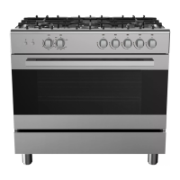
This document is a service manual for a Midea free-standing oven, specifically models with a 90x60 gas cooktop and an electric oven. It is intended for professional technicians with relevant qualifications, as incorrect maintenance can lead to hazards. Safety is paramount, requiring the power and gas supply to be cut off before any maintenance. If the power cord shows hidden malfunctions, it must be replaced with one meeting technical requirements (AWG2 + AWG101, resisting temperatures > 60℃). Any apparatus within 50mm of the product must withstand temperatures exceeding 75℃ to prevent deformation. Packaging materials like metal sheets, bags, foam, and screws should be kept out of reach of children to avoid suffocation or ingestion. The product must not be used until post-maintenance tests are conducted according to regulations. This manual applies to multiple models, so specific operations may vary.
The oven's dimensions are provided for reference, with an appliance width of 600mm, depth of 600mm, and height ranging from 855-920mm, with a cooktop height of 40mm and a back panel height of 22mm.
Function Description:
The appliance features a gas cooktop with five flame throwers, each controlled by a corresponding switch (Switch 1-5 from left to right). The electric oven offers a variety of functions and power outputs:
- Lamp: 96W
- Fan: 162W
- Heating element (upper) + infrared element + fan + rotary barbecue + lamp: 2966W
- Heating element (upper) + infrared element + rotary barbecue + lamp: 2900W
- Infrared element + rotary barbecue + lamp: 1900W
- Heating element (upper) + heating element (bottom) + fan + lamp: 2862W
- Heating element (upper) + heating element (bottom) + lamp: 2796W
- Heating element (bottom) + lamp: 1796W
- Heating air + lamp: 2562W
Usage Features:
When moving or lifting the oven, the door should be opened to access the upper and back parts of the oven cavity. The door handle should not be used directly for lifting. The oven must be placed on a flat surface to ensure stability. All flammable, combustible, and non-heat resistant articles must be kept away from the oven's surroundings.
Maintenance Features:
The manual provides detailed instructions for disassembly, troubleshooting, and maintenance.
Disassembly:
- Cooktop: Remove pan supports, sprayers, and burner caps. Lift the cooktop lid and unscrew the screws on the burner cup. Unscrew the rear section, then gently lift the rear of the cooktop and push it forward.
- Knob: Lift the knob base and pull it out.
- Drawer: Open the drawer to its maximum angle and remove the four screws attaching it to the hinge.
- Oven Door: Refer to the instruction manual for "Removing and fitting the appliance door."
- Inside Structure Overview: Key components include the thermo switch (55°C, normal open), main gas tube, flame ignitor, cooling motor, rotating motor, valve body (x5), bottom cup (x5), upper heating element, lamp, and terminal block.
- Upper Heating Element: Disassemble the rear panel. Pull out the terminal of the upper heating element. Open the oven door, remove the cooking grid(s) and cooking pan. Unscrew four screws to remove the upper heating element.
- Bottom Heating Element: Disassemble screws and open the rear panel. Pull out the terminal and unscrew the bracket of the bottom heating element.
- Oven Lamp: Disassemble the cooktop and pull out the lamp wire and ground wire. If the bulb needs replacement, screw off the bulb cover from the cavity.
- Rotary Motor: Disassemble the control panel. Disassemble the left side board to expose the rotary motor. Pull out the wire harness from the rotary motor. Remove the rotary motor by loosening the fixed screws at both ends of its support.
Troubleshooting:
- Gas Troubleshooting:
- Yellow flame: Check if the gas source and pressure conform to requirements.
- Burner flames out: Check if the gas source conforms to requirements.
- Burner cannot be ignited easily: Check gas source and pressure, inspect burner ignition holes for blockages or burrs, and ensure the fire-conductive leaf overlaps with the flash hole.
- No suction of flame-out protection valve and temperature controller valve: Check if the flame ignites the thermocouple, inspect the joint between thermocouple and electromagnetic valve for looseness or cut wires, and adjust the distance between the thermocouple head and burner to 2-4mm.
- Electronics Troubleshooting:
- Heating elements not heated: Replace the heating element, change the wire harness, or change the control switch.
- Oven lamp not lighting up: Replace the oven lamp, change the wire harness, or change the lamp control switch.
- Ignition needle not striking fire: Replace the pulse igniter, replace the ignition needle, change the wire harness, or change the ignition control switch.
- Rotary motor not rotating: Replace the rotary motor, change the wire harness, or change the rotary control switch.
- Important Note: Always check the ground wire before troubleshooting electrical faults, and pay close attention to high voltage circuits.
Maintenance and Test:
- Air Leakage Test:
- Professional Procedure: Connect to an air leakage device, set pressure to 15kPa. With the plug valve closed, test gas pipelines for leakage. With all plug valves open and the burner injector blocked (flame-out protection valve open), test gas pipelines for leakage. Leakage must be below 0.5mL/min.
- Simple Procedure: Connect the product to the gas supply. Smear soap water on all joints of the gas pipelines with the plug valve closed, checking for bubbles. Then, with all plug valves open and the burner injector blocked (flame-out protection device valve open), smear soap water on all joints and check for bubbles. No air bubbles should be detected.
- Important Note: Components of the gas pipelines should only be disassembled or replaced if air leakage is confirmed to conform to relevant requirements.
- Replacement of Injector and Adjustment of Valve:
- Tools: Inner hexagon S7 sleeve, 2mm straight screwdriver.
- Steps: Disassemble the cooktop and injectors. Select the correct substitute injector from the provided table, apply thread sealant, and reassemble. Switch on the gas, ignite the burner, and turn to small fire mode. Pull out the knob, use a screwdriver to adjust the valve core through the small holes until a moderate small flame (4mm higher than the burner) is observed. Adjust the lower burner fire until a moderate small flame is seen with no flameout when the door is closed.
- Replacement of Valve Body:
- Tools: Screwdriver, open spanner.
- Steps: Disassemble the thermocouple and aluminum gas tube connected to the valve body. Unscrew the mounting valve screws. Assemble the new valve by reversing these steps, connecting the aluminum gas tube and thermocouple.
- Replacement of Gas-type Fitting:
- Tool: Open spanner.
- Steps: Disassemble the gas-type fittings from the main gas tube. When replacing, ensure they are tightly locked onto the main gas tube. The fittings include a gas tube, seal washer, and joint.