E N G L I S H
2
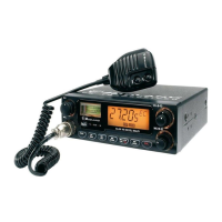
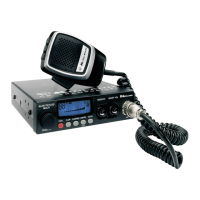
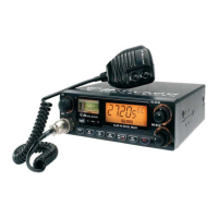
FUNCTION AND LOCATION OF THE CONTROLS
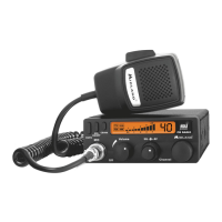
1. Channel selector
2. Multifunction backlighted display. It shows:
A. Frequency band selected.
B. Channel selected number
C. EMG mode
D. AM/FM mode
E. RX/TX:TX=transmit mode; RX=receive mode
F. LOW: displayed when the radio transmits in low power (this mode is possible with
some frequency bands only – see the Frequency band chart)
G. The received signal strength and the power of the transmitting signal
3. Button for changing colour: by pushing a pointed object into the hole, you can change
the backlight colour of the display. You can choose amongst the following colours:
white, yellow, violet, red, light blue, green, blue or no colour.
4. “AM/FM”(LCR) button: To select AM or FM mode. If you select a frequency band
operating in FM mode only, this button enables the LCR function (Last Channel
Recall).
5. “Squelch” Control: For the maximum receiver sensitivity, the control must be regulated
exactly where the receiver background noise disappears.
6. “ON/OFF Volume” Control. In “OFF” position your transceiver is OFF. Turn this control
clockwise to switch on the unit. Turn the knob clockwise a little more to set the audio
level, until you get a comfortable reception.
7. Microphone jack: Insert the mic connector into this jack.

 Loading...


