E N G L I S H
3
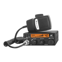
REAR PANEL
8. ”EXT” jack: external loudspeaker jack.(the internal loudspeaker is excluded)
9. Power 13.8V DC: power supply cable
1
0. S.Meter jack: it allows an external “S. Meter” connection
11.
Antenna connector (SO239 connector type)
MICROPHONE
1. PTT: transmission button
2. UP/DOWN buttons: manual channel selector.
3. 6 pin microphone connector
INSTALLATION
Safety and convenience are the primary consideration for mounting any piece of mobile
equipment. All controls must be readily available to the operator without interfering with
the movements necessary for safe operation of the vehicle. Set the proper position in the
car to install the transceiver using the supplied supporting bracket or eventually the slide
bracket.
Tighten the retaining screws. The xing bracket must be close to metallic parts.
POWER SUPPLY
Be sure the transceiver is OFF. In the direct-voltage power supply, it is very important to
observe the polarity even if the unit is protected against the accidental inversion:
Red = positive pole (+)
Black = negative pole (-)
The same colours are present on the battery and in the fuse box of the car. Correctly
connect the cable terminal to the battery.
 Loading...