4.2 Location for the transceiver
Before continuing, look for a place to install the transceiver which:
Is far enough away from any device sensitive to magnetic/electromagnetic elds•
(e.g. compass) in order to avoid interference during their use.
Allows for accessibility to the front panel of • NEPTUNE 100.
Provides easy connection to a power supply, for the antenna and for other cables.•
Has sufcient space close by for installation of the microphone support.•
Allows for mounting of the antenna at least 1 meter from the transceiver.•
The universal mounting bracket supplied allows for mounting of the transceiver high up (with2
the bracket above the device) or on the bridge (with the bracket below the device) with an
angle range of 45°.
Warning! Installation and connections must be performed in part by qualied persons.
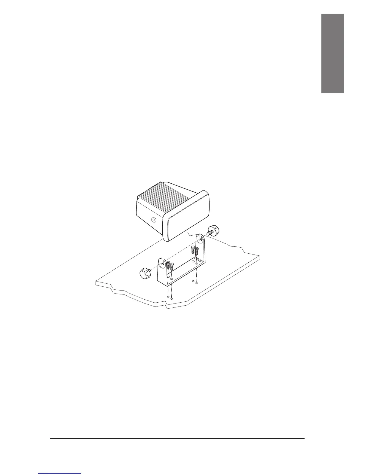
4.3 Mounting of transceiver
To mount the transceiver to your vessel (see following picture):
Choose an appropriate location, as explained in the paragraph above.1.
Position the mounting bracket on the surface upon which it will be xed, use a pencil to draw the2.
position of the four holes where the screws will be inserted.
Ensure that the surface intended for the transceiver mounting can be drilled into without
provoking damage to other parts of the vessel and be careful to not drill right through
it.
Remove the bracket, drill four holes smaller in diameter than the screws, and reposition the3.
mounting bracket, aligning it with the four holes.
Screw in the mounting screws and ensure the bracket is xed rmly, using the screws, the4.
grained washers, the at washers and the nuts supplied.
If you are not able to reach the back part of the bracket surface to x the nuts onto the
screws, use threaded screws to x the bracket.
Tighten the screws with a screwdriver so that the bracket is rmly xed to the surface.5.
Align the transceiver on the bracket, ensuring the holes of the internal part of the bracket line up6.
 Loading...