SYN-TECH III P25 PORTABLE RADIO
SERVICE MANUAL
4-3
4.4 ADJUSTMENT PROCEDURES
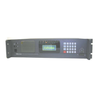
a. Connect the equipment as illustrated. (Figure 4.1)
b. Set the Power Supply output voltage to 7.5V and current limit to 2A.
c. Set the RF Signal Generator output to its minimum level.
d. Set the Audio Analyzer output impedance to 600 and amplitude to 0V
rms
.
e. Set the Modulation Analyzer to measure +/-peak deviation. Set the audio bandwidth for ≤ 5Hz to ≥ 15
kHz. Turn the de-emphasis function off.
f. Run MRA.exe on the PC.
g. Click on the Read Radio icon and enter the “Radio Adj.” menu.
h. Adjustments specified in steps 4.4.1 - 4.4.10 should be applied consecutively.
i. Adjustments specified in steps 4.4.1 - 4.4.10 should be applied to all models unless otherwise
specified.
j. If “Analog Frequency Adjustment” is changed, then “C4FM Receive Level Adjustment” has to be
repeated.
k. If “Modulation Flatness Adjustment” or “Modulation Limiting Adjustment” is changed, then the
successive modulation and deviation adjustments have to be repeated.
NOTE: The alternative test equipments, which can be used in the adjustment set-up, should be
compatible to those specified in EIA-603-B and/or TIA-102.CAAA-B standards.
4.4.1 RF Output Power Adjustment
a. Enter “RF Output Power Adjustment” window and click “Transmit”.
b. Adjust RF Output Power Parameter to obtain the measured power levels to be equal to the selected
power levels for each selected frequency.
4.4.2 Analog Frequency Adjustment 25 kHz
a. Enter “Analog Frequency Adjustment 25kHz” window and click “Transmit”.
b. Adjust until the frequency error is less than 10Hz on the test frequency.
4.4.3 Digital Frequency Adjustment
a. Enter “Digital Frequency Adjustment” window and click “Transmit”.
b. Adjust until the frequency error is less than 10Hz on the test frequency.
4.4.4 Modulation Flatness Adjustment
a. Enter “Modulation Flatness Adjustment” window, select the lower test frequency and click “Transmit”.
b. Set the audio signal frequency to 20Hz and adjust the audio signal level to obtain 3000Hz deviation
on Modulation Analyzer. The audio signal level should be 250±50mV
rms
at the OPT-1 (Ext-Mic) input
of the radio.
c. Set the audio signal frequency to 20Hz, click “MOD-2” and set the measured audio signal level on
Audio Analyzer as 0.0dB reference.
d. Set the audio signal frequency to 2000Hz, click “MOD-1” and adjust MOD-1 parameter to obtain
0.0±0.05dB audio signal level on Audio Analyzer.
 Loading...