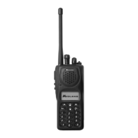
SYN-TECH III P25 PORTABLE RADIO
SERVICE MANUAL
4-4
e. Repeat the steps ”c” and “d”.
f. Select the medium test frequency.
g. Set the audio signal frequency to 20Hz, click “MOD-2” and adjust MOD-2 parameter to obtain
0.0±0.05dB audio signal level on Audio Analyzer.
h. Set the audio signal frequency to 2000Hz, click “MOD-1” and adjust MOD-1 parameter to obtain
0.0±0.05dB audio signal level on Audio Analyzer.
i. Repeat the steps “g” and “h”.
j. Select the higher test frequency and repeat the steps “g” and “h”.
k. Repeat the step”j”.
4.4.5 Modulation Limiting Adjustment
a. Enter “Modulation Limiting Adjustment” window and click “Transmit”.
b. Set the audio signal frequency to 1 kHz and level to 2 times of the level in step 4.4.4 “b” at OPT-1
input.
c. Adjust Modulation Limiting until deviation is ±4600±50Hz.
4.4.6 FM Deviation Adjustment
a. Enter “FM Deviation Adjustment” window and click “Transmit”.
b. Set the audio signal frequency to 1 kHz and level to 100mV
rms
at OPT-1 (Ext. Mic) input.
c. Adjust FM Deviation parameter until deviation is ±4400±50Hz.
d. Set the audio signal amplitude to 0mV
rms
.
4.4.7 C4FM Deviation Adjustment
a. Enter “C4FM Deviation Adjustment” window and click “Transmit”.
b. Adjust C4FM Deviation until deviation is 2800±30Hz.
4.4.8 Squelch Adjustment
a. Enter “Squelch Adjustment” window.
b. Set the RF signal frequency to the test frequency, modulation frequency to 1 kHz, deviation to 3 kHz
and adjust the RF signal level for 10dB SINAD. The RF level input at the antenna should be less than
–119dBm.
c. Adjust the Squelch setting until the RX LED is off, and then to the position where RX LED is just on or
click “AUTOMATIC” for the automatic adjustment.
d. Adjust the RF signal level in 0.2dB increments from RX LED ON condition to the position where RX
LED is just off and record the RF input level at the antenna as Squelch Closing Level.
e. Adjust the RF signal level in 0.2dB increments from RX LED OFF condition to the position where RX
LED is just on and record the RF input level at the antenna as Squelch Opening Level.
f. Squelch Opening Level should be less than -119dBm, the ratio between Squelch Opening Level and
Squelch Closing Level should be 2.5 ±1.0dB and SINAD at Squelch Opening Level should be 10
±2dB.

 Loading...