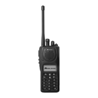
SYN-TECH III P25 PORTABLE RADIO
SERVICE MANUAL
7-4
As shown in the picture below, flexible circuits are separated from the connectors using tweezers.
There is a connection point on the main board that connects the RF and Control
Board to the antenna connector. This part must make contact with the antenna
connector (in the front panel) during assembly as shown below.
The PCB assembly is now free from its connections and can be separated from the front panel.

 Loading...