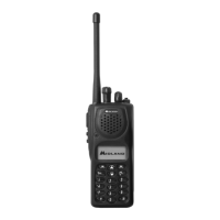
SYN-TECH III P25 PORTABLE RADIO
SERVICE MANUAL
v
8.4 UHF RF SCHEMATIC 450-512 MHz................................................................................................ 8-5
8.5 CONTROL SCHEMATIC.................................................................................................................. 8-6
8.6 DSP SCHEMATIC ............................................................................................................................8-7
8.7 LCD AND KEYPAD SCHEMATIC .................................................................................................... 8-8
FIGURES
Figure 3-1: Midland Syn-Tech III P25 Portable Radio Connection Diagram .................................................. 3-1
Figure 4-1: Adjustment Setup .........................................................................................................................4-2
Figure 6-1: Main Assemblies Location Diagram ............................................................................................. 6-2
Figure 6-2: PCB Assemblies Location Diagram..............................................................................................6-4
Figure 6-3: Rear Panel Assembly Location Diagram......................................................................................6-6
Figure 6-4: Front Panel Assembly Location Diagram ..................................................................................... 6-8
Figure 6-5: Display and Keypad PCB Location Diagram -1..........................................................................6-10
Figure 6-6: Display and Keypad PCB Location Diagram -2..........................................................................6-11
Figure 6-7: DSP PCB Location Diagram -1 ..................................................................................................6-14
Figure 6-8: DSP PCB Location Diagram -2 ..................................................................................................6-15
Figure 6-9: VHF RF and Control PCB Location Diagram -1 ......................................................................... 6-17
Figure 6-10: VHF RF and Control PCB Location Diagram -2 ....................................................................... 6-18
Figure 6-11: UHF RF and Control PCB Location Diagram -1....................................................................... 6-24
Figure 6-12: UHF RF and Control PCB Location Diagram -2....................................................................... 6-25
TABLES
Table 2-1: Syn-Tech III P25 Portable Radio General Specifications .............................................................. 2-2
Table 2-2: Batteries for Syn-Tech III P25 Portable Radios.............................................................................2-2
Table 2-3: Syn-Tech III P25 Portable Radio Environmental Specifications.................................................... 2-2
Table 2-4: Syn-Tech III P25 Portable Radio Receiver Specifications ............................................................ 2-3
Table 2-5: Syn-Tech III P25 Portable Radio Transmitter Specifications ........................................................2-4
Table 3-1: KN1, RF and Control PCB to DSP PCB Signals ...........................................................................3-6
Table 3-2: KN2, RF and Control PCB to Display and Keypad PCB Signals .................................................. 3-7
Table 4-1: Spurious Signal Frequencies.........................................................................................................4-1
Table 5-1: Syn-Tech III P25 Portable Radio Error Messages......................................................................... 5-1
Table 5-2: Syn-Tech III P25 Portable Radio Alert Messages .........................................................................5-2
Table 5-3: Syn-Tech III P25 Portable Radio ‘Problem-Solution’ Table........................................................... 5-3
Table 6-1: Main Assemblies Parts List............................................................................................................6-3
Table 6-2: PCB Assemblies Parts List ............................................................................................................ 6-5
Table 6-3: Rear Panel Assembly Parts List .................................................................................................... 6-7
Table 6-4: Front Panel Assembly Parts List....................................................................................................6-9
Table 6-5: Display and Keypad PCB Parts List ............................................................................................6-12
Table 6-6: DSP PCB Parts List .....................................................................................................................6-16
Table 6-7: VHF RF and Control PCB Assembly Parts List ...........................................................................6-19
Table 6-8: UHF RF and Control PCB Assembly Parts List...........................................................................6-26

 Loading...