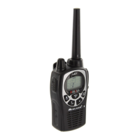
Midland
XT511
ALIGNMENT PROCEDURE
www.radioaficion.com
1. REFERENCE TEST EQUIPMENT
• A. HP8921A Cell site test set or HP8920A, B Communication Test Set with
Spectrum
Analyzer option.
• B. Fluke 187 Digital Voltmeter
• C. HP E3615A Power supply
2. TEST POINT
A. ANTENNA : Test point is not prepared. Use antenna contact with
ANTGND1(antenna ground).
B. GMRS VCO reference voltage: Test point 1 is prepared.
C. RX audio output : Speaker terminals & ear jack are prepared.
D. TX Mic. Input : Use ear-jack(3.5mm) with 10uF coupling capacitor.
E. Battery Vcc : Test point is not prepared. Please use mechanical contact.
Plus terminal is posited on upper right corner of PCB (Battery
cover side view).
F. Call Key : Test point UP is prepared.
G. Menu Key : Test point MENU is prepared.
H. Monitor Key : Test point MONITOR is prepared.
I. PTT Key : Test point PTT is prepared.
J. Scan key : Test point SCAN is prepared.
Note. : All key can be activated when connect with ground.
3. VCO ALIGNMENT
A. Set unit to Channel 1 and connect a voltmeter to TP1 (VCO PD).
B. Press & hold PTT.
C. Extend L141 until the voltmeter reads 1.5V.
D. Put shield-can on VCO area and monitor the voltage on TP1. The voltage should be
1.5Vdc +/-0.2Vdc. If the voltage is not 1.5Vdc +/-0.2Vdc, realign L141 until meet to
requirement.
E. Release PTT button so units is in receiving mode and monitor the voltage on TP1. The
voltage should be in the range 1.5Vds +/-0.5V
F. Set unit to channel 14.
6. Press & hold the PTT switch and observe the voltage on TP1. The voltage should be 2 -
3,5 Vdc.
7. Release PTT and observe the voltage on TP1. The voltage should read between 2.0 - 3.5
Vdc.
Note : VCO shield-can should be soldered after VCO alignment is finished.
4. TRANSMITTER FREQUENCY ALIGNMENT
A. While Press & hold the PTT, Menu and Menu buttons, the knob clockwise to switch on the
radio..
B. Align Up or Down button such that the output frequency is equal to the channel frequency
with a maximum error of +/- 200 Hz.