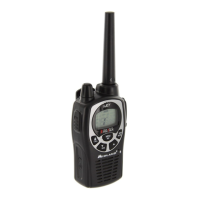
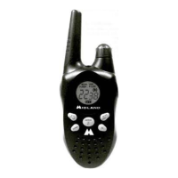
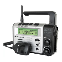
XT511 CAMP RADIO
LABORATORY TESTING PROCEDURES
UNIT TEST - (UNIT ASSEMBLED)
TEST PREPARATION
1) Install 4 “AA” alkaline batteries (observe polarity markings).
- Left upper terminal is the system plus polarity
- Right bottom terminal is the system minus polarity.
2) Turn on unit by pressing the power button.
SYSTEM TEST
1) Radiated Transmit and Receive performance may be observed.
2) Audio out & Audio in are available at the Headset jack.
LABORATORY TEST - (UNIT UN-ASSEMBLED)
TEST PREPARATION
1) Disassemble unit (8 screws - 5 behind battery cover). Remove the PCB from the
cabinet.
2) Remove the antenna and install a 50 ohm coax cable in its place.
3) Either clip alligator leads or solder test leads to the power supply connections. The
positive terminal is the lower right PCB mounting hole. The negative terminal is the
lower left PCB mounting hole below the VCO shield can. (battery side view)
4) Connect 6VDC power source to the terminals, observing correct polarity.
5) Connect an 8 ohm load through the Headset jack (3.5mm stereo-phone right plug).
6) Connect a audio generator with 10uF coupling capacitor through the Headset jack
( 3.5mm stereo-phone left plug).
7) Select desired channel 1-22 using CH up/down keypad switch. The rubber keypad
may be removed from the front cabinet and used directly on the PCB.