Technical Information
94
G 1xxx/G 2xxx
accurately registered in the following measuring process.
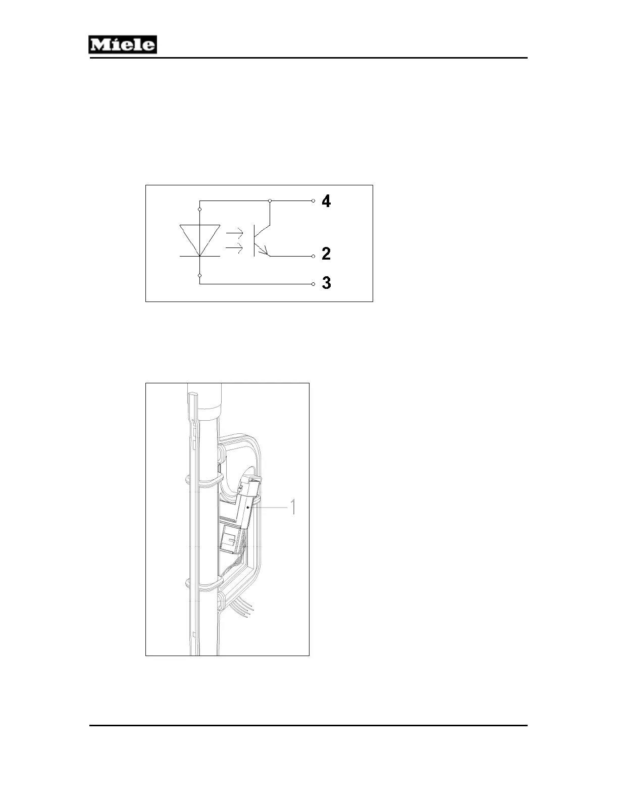
A photoelectric barrier switch (infrared (IR) diode opposite a phototransistor)
acts as a turbidity sensor. Depending on the turbidity (transparency) of the
water, a certain current flows through the phototransistor. This current is
measured and processed by the electronic which then initiates the
appropriate action. If the level of turbidity passes certain thresholds, then,
depending on the soiling detected, subsequent cleaning cycles are modified
accordingly with regard to water quantity, program duration and temperature.
Figure 050-12: Turbidity Sensor Circuit
2
Light receiver output (emitter)
3
IR LED cathode
4
Common 5V
The sensor is situated in the feed pipe to the top spray arm; see Figure 050-13,
Item 1.
Figure 050-13: Turbidity Sensor Location

 Loading...