16
INITIAL INSTRUCTIONS
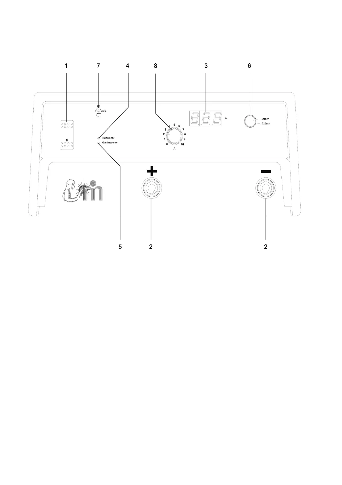
BOX 3, MMA
General
1. Main switch
This control switches the machine on and off.
2. Welding cable plug
3. Digital display
The control panel is fitted with a display which
shows the welding current. At stand-by the set
welding current is shown. When welding the
average welding current is shown. Please note
that during 'START UP' and when error
messages, for instance overheat, are displayed
the digital readings may be displayed incorrectly.
4. Mains error
Cause: Excessive or insufficient mains
voltage.
Symptoms: The welding process stops. This
error is indicated by the red light
emitting diode and the words
"Mains error".
Action: Adjust mains voltage.
5. Overheating error
Cause: Overheating of an inverter module
due to incorrect use, or fault in the
inverter module.
Symptoms: The welding process stops. This
error is indicated by the yellow light
emitting diode and the words
"Overheating error". This LED
switches off after 7 - 10 min. if the
error is not corrected. When pres-
sing the trigger, the LED switches
on again.
Action: If the error has not been caused by
incorrect use, call in service staff.
6. INT/EXT control
This switch enables selection between inter-
nal/external control of the welding current. When
in internal position, the current is set on the
machine.
When in external position, the current is set
through a remote control. Slope-up, pulse wel-
ding, welding with reduced current and slope-
down are also possible through remote control.