28
rev 12.14.15
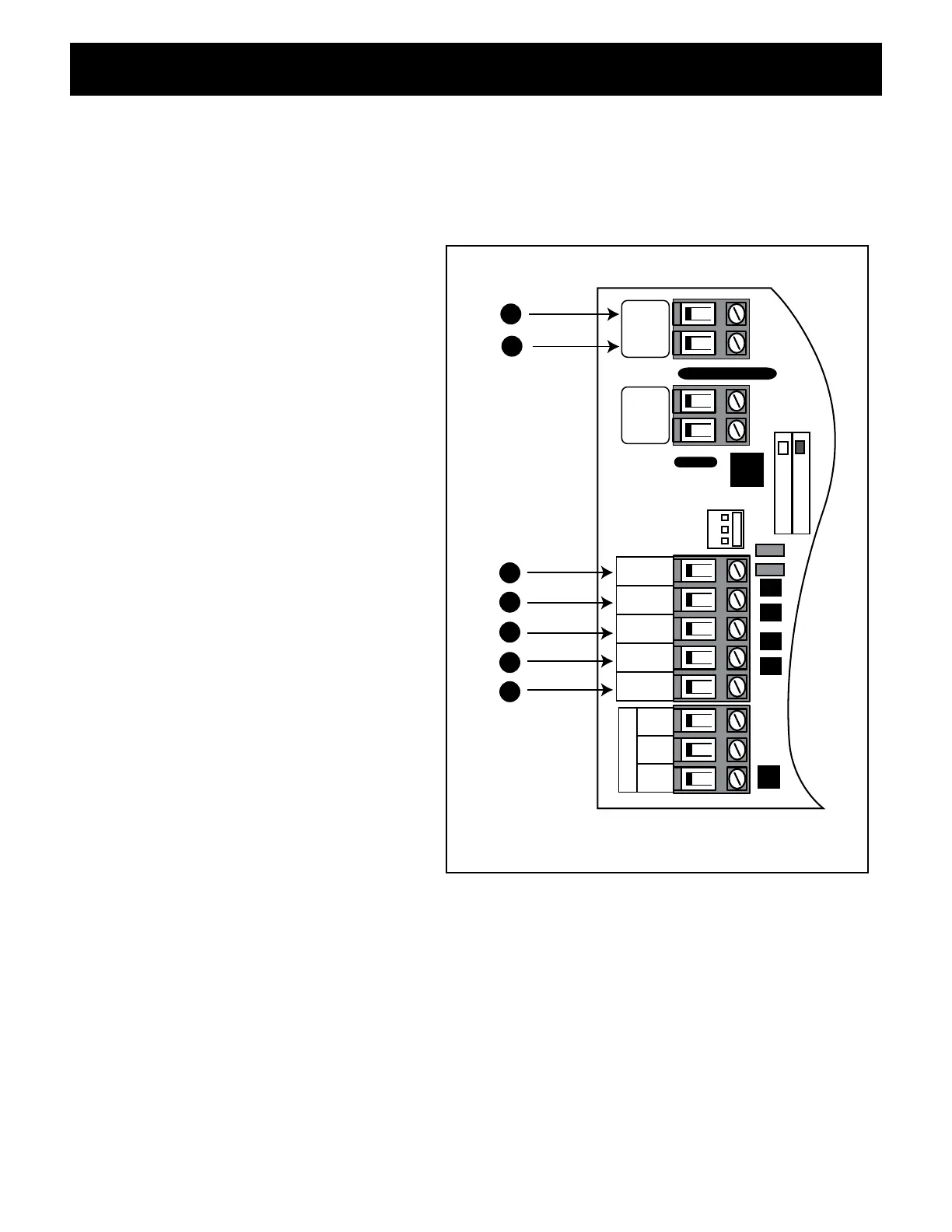
Input Connections
• All control inputs are dry-contact, normally open, inputs. DO NOT apply external voltage sources
to these inputs.
• All inputs are connected with respect to COMMON terminal.
• The status LED will blink once when any input is activated.
1 COMMON: Circuit common (reference
for all logic input)
2 CYCLE: (Typically for use with push
button or hard-wired keypad)
• Each activation at this input will cycle
the operation as follows:
OPEN–STOP–CLOSE–STOP–OPEN
3 EDGE: (Typically for use with safety
edge device)
• Activation of this input while the
gate is closing will cause the gate
to stop and reverse direction for
approximately 2 seconds.
• Activation of this input while the gate
is opening has no effect (gate will
continue to open).
• Activation of this input while gate is
idle will prevent gate from closing.
4 SAFETY: (Typically for use with photo
beam device, loop detector or other
non-contact sensors)
• Activation of this input while the gate
is closing will cause the gate to stop
and return to the opened position.
• Activation of this input while the gate
is opening has no effect (gate will
continue to open).
• Activation of this input while gate is
idle will prevent gate from closing.
5 EXIT: (Typically for use with exit loop or wand)
• Activation of this input will open the gate if it’s not already at the open position
• Activation of this input while at open limit will restart the auto close time (if enabled).
6/7 AUX/OUT: Multi-function output: refer to DIP Switch 4 on page 23.
CHARGING
POWER
RCVR
GRN
BLK
RED
EXIT
SAFETY
EDGE
CYCLE
COMMON
LINK
AUX
OUT
SOLAR
INPUT
18VAC/
H L
1
2
3
4
5
7
6
CONNECTING ACCESSORIES