Printed in China for GTO Access Systems, LLC.
Copyright
©
2016 GTO Access Systems, LLC
Document Number: R56208 REV A (12.19.16)
GTO Sales: 800-543-4283 • Fax 850-575-8912
GTO Technical Service 800-543-1236
For 24 hour/day, 7 day/week Technical Service visit http://support.gtoinc.com
For more information on Mighty Mule’s full line of Automatic Gate Operators and Access Controls visit
www.mightymule.com
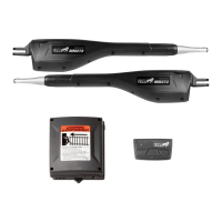
MM562
ACCESS SYSTEMS, LLC
Mighty Mule® is the retail brand of GTO Access Systems, LLC
3121 Hartseld Road • Tallahassee, FL 32303
This product meets the requirements of UL325 6th Edition, 2016, the standard for gate
operator safety.
Installation Manual
Horizontal Support
Gate Swings Evenly and Freely
Hung Firmly and Plumb
Receiver
Post Bracket
Control Box with Battery
Fence Post Set in Concrete
Run 1000' (max.) of low
voltage wire to control
box from transformer
(wire not included).
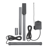
Power Cable
PVC conduit (not included)
to protect wire from lawn
mowers and weed eaters.
PVC conduit (not included)
to run second opener power
cable under driveway.
Gate Bracket
Warning Sign
First Gate Opener
Second Gate Opener
Horizontal Support
Post Bracket
Gate Bracket
120 Volt indoor
Transformer
(surge protector
not supplied)
Example of nished installation
(installations vary slightly on different types of gates)