9
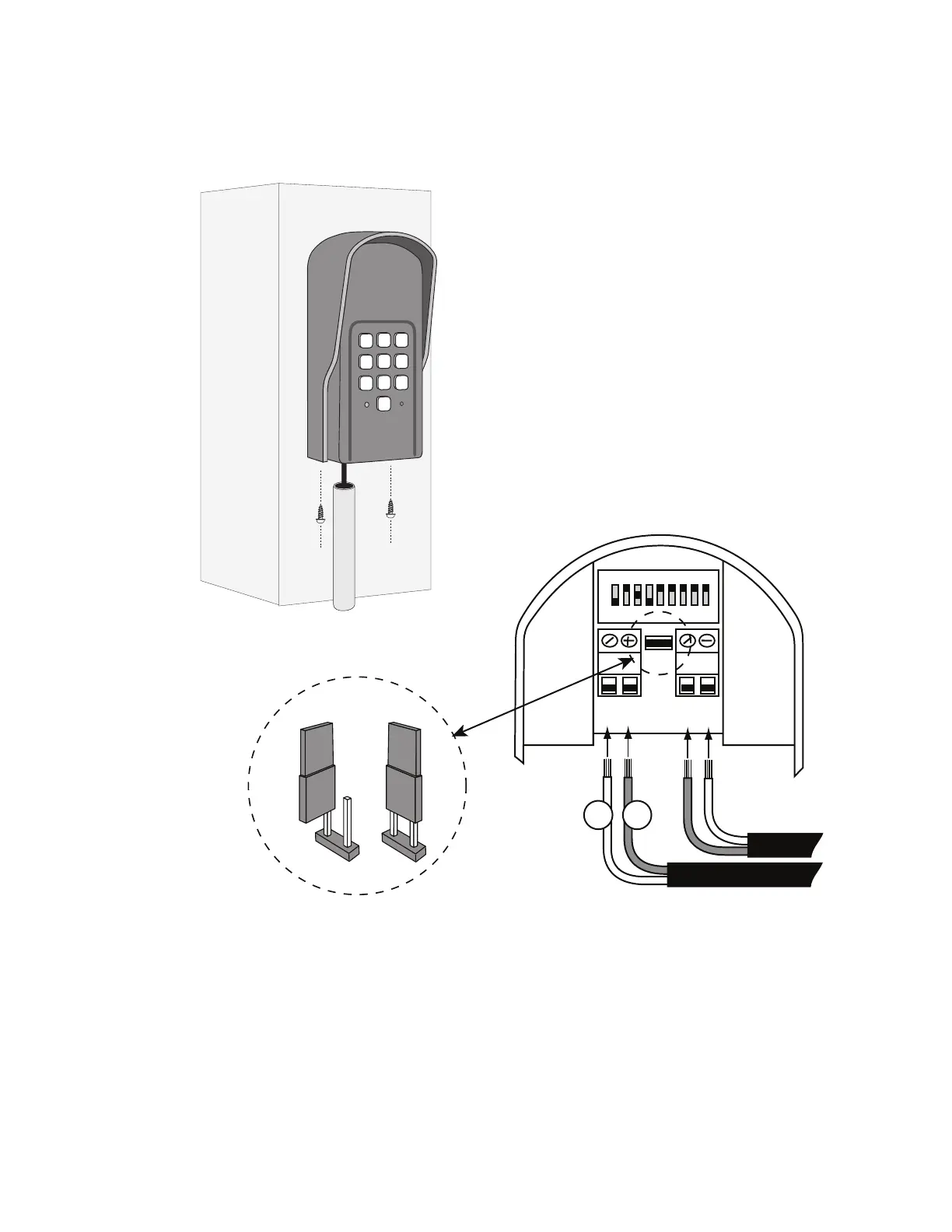
Step 5: Attach the wires from the keypad to the opener control board terminal blocks as shown in wiring diagrams below.
Step 6: Replace the control board cover and turn the power switch ON. Test the keypad by entering 1 2 3 4.
Step 7: Program your “Personal Master Code” and any additional entry codes (for a total of 25 entry codes) you wish. See
Programming the Keypad section.
1
2
ABC
3
DEF
4
GHI
5
JKL
6
MNO
7
PRS
8
TUV
9
WXY
0
RELAY
OUTPUT
AC/DC
POWER IN
123456789
+
0
–
Jumper ON
Jumper OFF
Hard-wire from Gate Opener
Power Supply fr
Opener Battery
#
1
#
2