10
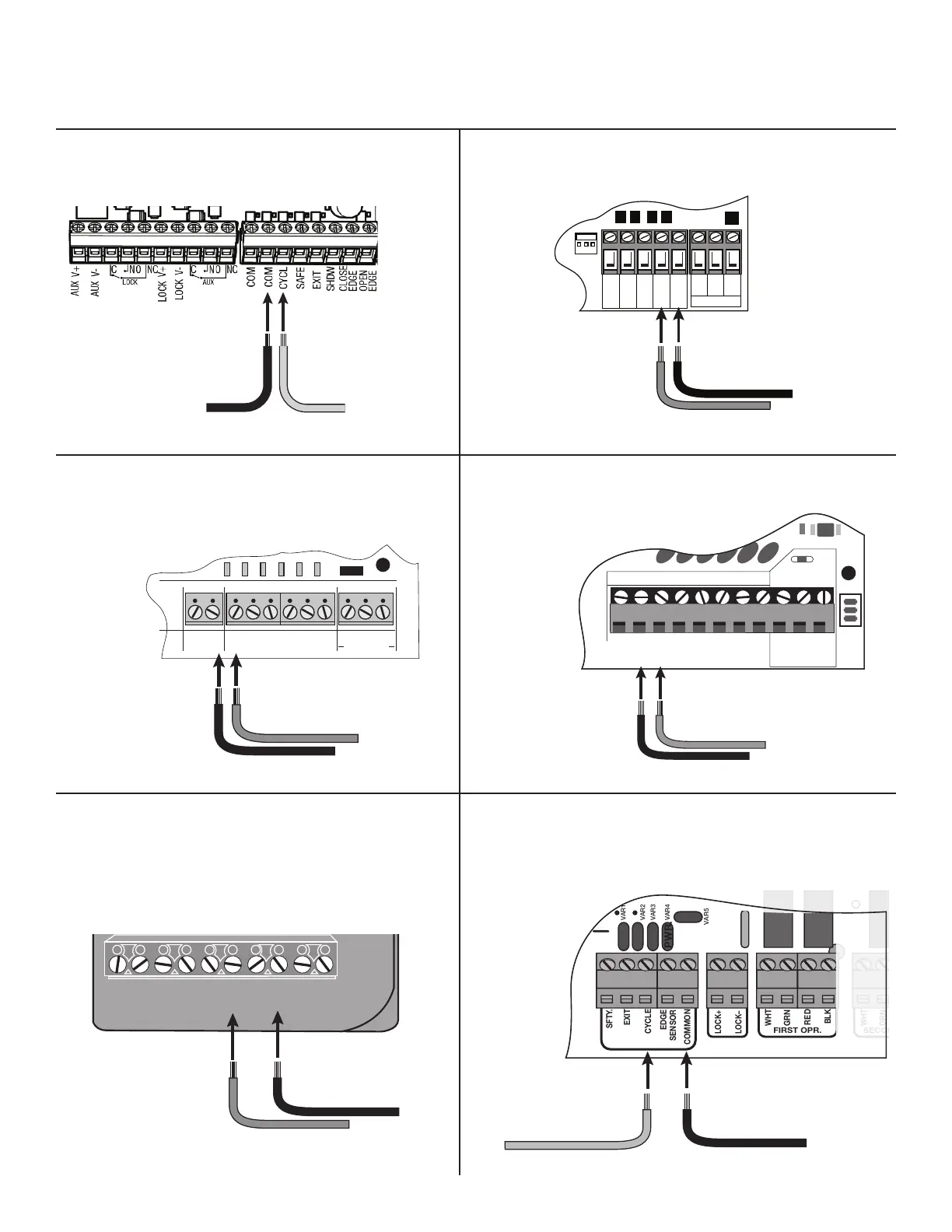
Connect #2 wire from the RELAY
OUTPUT terminals on the keypad to
the COM terminal on the gate opener
control board.
Connect #1 wire from the
RELAY OUTPUT terminals
on the keypad to the
CYCLE terminal on the
gate opener control board.
#2 #1
Control Board Connections
NOTE: If your control board doesn’t look like any of these diagrams, please call Technical Service at 1-800-543-1236 or 850-575-4144 for
additional support.
Connect #2 wire from
the keypad to the COM
terminal on the gate
opener control board.
Connect #1 wire from the
RELAY OUTPUT terminals
on the keypad to the
CYCLE terminal on the
gate opener control board.
#2
#1
POWER
LED3
D15
R20
IC4
D16
D13
D14
K2
BATT- BATT+
EDGE
COM
LOCK+
LOCK -
M_BLK
GRN
VAR3
VAR3
VAR1
VAR4
VAR5
PF1
VAR6
WHT
CYCLE
EXIT
SAFETY
COM
CHGR
CHGR
RECR
GRN
BLK
RED
EXIT
SAFETY
EDGE
CYCLE
COMMON
LINK
Connect #1 wire from the
RELAY OUTPUT terminals
on the keypad to CYCLE
terminal on the gate opener
control board.
Connect #2 wire from the RELAY
OUTPUT terminals on the keypad
to the COMMMON terminal on
the gate opener control board.
#1
#2
RECEIVER
COM COM
CYCLE
CLOSE
SAFETY
EXIT/
OPEN
SHADOW
LOOP
CLOSE
EDGE
OPEN
EDGE
BLKGRN RED
Connect the #1 wire from
RELAY OUTPUT terminals on the
keypad to the CYCLE terminal on
the opener control board.
Connect the #2 wire from
the RELAY OUTPUT
terminals on the keypad to
one of the COMMON
terminals on the opener
control board.
#1
#2
RECEIVER
ALM
RCVR.
COM
GRN
BLK
RED
CYCLE
SAFETY
EXIT
SHADOW
OPEN
EDGE
COM
CONTROL INPUTS
CLOSE
EDGE
Connect #1 wire from
the RELAY OUTPUT terminals on
the keypad to CYCLE terminal on
the gate opener control board.
Connect #2 wire from the
RELAY OUTPUT terminals
on the keypad to the COM
terminal on the gate opener
control board.
#1
#2
Connect #1 wire from the
RELAY OUTPUT terminals
on the keypad to CYCLE
terminal on the gate opener
control board.
Connect #2 wire from the
keypad to the COMMON
terminal on the gate opener
control board.
#1
#2
VAR5
K1
PF1
K2
BATT +
K3
K4
VAR4
VAR3
VAR2
VAR1
PWR.
SFTY.
EXIT
CYCLE
EDGE
SENSOR
COMMON
LOCK+
LOCK–
WHT
GRN
RED
BLK
WHT
GRN
SECOND OPR.FIRST OPR.
RED
BLK
14 VAC
OR
SOLAR
Mighty Mule MM371, MM372, MM571,
MM572 and TS 571 Control Boards
Mighty Mule 500 & 502 Control Boards
MM271 Control Boards
Mighty Mule 360 Control Board
MM560, MM562, MM660, PRO3000XLS Series,
and PRO4000XLS Series Control Boards
MM262, MM362, MM462, FM202,
PRO-SW2000XLS Series Control Boards