INSTALLATION
TECHNICAL DOCUMENTATION 19
CONDENSE CONNECTIONS
The boiler includes an anti syphon condense trap enabling the condense pipework to be taken directly to
drain. The condense water is slightly acidic (pH 3.0 - 5.5) and should be run in a standard drain pipe material,
e.g. acrylonitrile-butadiene-styrene (ABS), polypropylene (PP), polyvinyl chloride (PVC), cross-linked polyvinyl
chloride (PVC-C) or unplasticised polyvinyl chloride (PVC-U).
The condensate pipe should ideally run and terminate internally to a soil stack or waste pipe. Alternatively, the
condensate can be discharged in to the rainwater system or a purpose-made soakaway. Whichever method
is used must conform to applicable national and local standards and regulations. All connecting drainage
pipework should have a fall of at least 2.5° to the horizontal, or approximately 25mm per metre of pipe run. If
the drainage pipe has external run it should be kept to a minimum length with a minimum diameter of 22mm
and be insulated in order to minimise the effects of freezing. It should be noted that connection of a
condensate pipe to a drain may be subject to building controls.
SAFETY VALVE CONNECTION
The discharge pipe from the safety valve shall be self draining and terminate in a visible position where the
discharge cannot result in hazard to any person or to the plant. The size of the discharge pipe shall be no less
than the nominal size of the valve outlet.
HYDRAULIC SYSTEM
The minimum required water circulation over the boiler should be maintained at all times (equivalent to ΔT
25°K at full load). The minimum required water circulation should not be adversely affected by the use of
valves, non-return valves, systems in which several boilers are connected to a common distribution pipe etc.
The maximum water flow is achieved at ΔT 15°K.
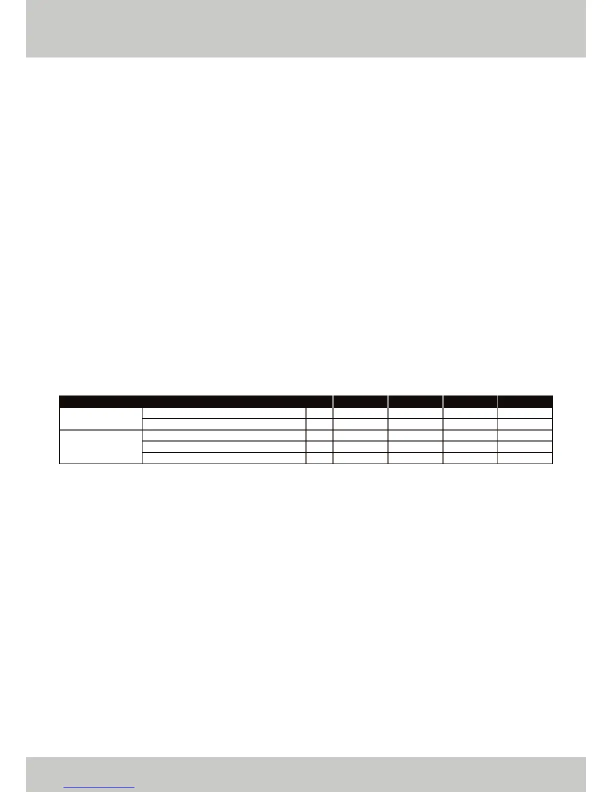
Pump Data
* Maximum power consumed is given in Pump Position 03.
The boiler has a pump control circuit. When the boiler is enabled, the pump is switched on. If the boiler is
disabled, the pump will continue to run for a few minutes. The standard run on time is two minutes, but this can
be adjusted.
ETHOS 130
5.57
31.0
40.0
9.0
140
ETHOS 110
4.71
22.5
52.0
29.5
140
ETHOS 90
3.86
24.5
66.0
41.5
140
ETHOS 70
3.00
45.0
82.0
37.0
140
m
3
/h
kPa
kPa
kPa
W
Nominal Flow Rate (Q)
Boiler Resistance Nominal Flow (R)
Pump Head at Nominal Flow (Q)
Available Head at Nominal Flow (Q)
Maximum Power Consumption*
▲ FIGURE 08. WATER FLOW QUANTITY AND PUMP DATA FOR THE WALL MOUNTED ETHOS RANGE.
ΔT 20°K
 Loading...