EasyManua.ls Logo

Miller Electric ProHeat 35 - User Manual

Miller Electric ProHeat 35
72 pages
Print Icon
To Next Page IconTo Next Page
Loading...
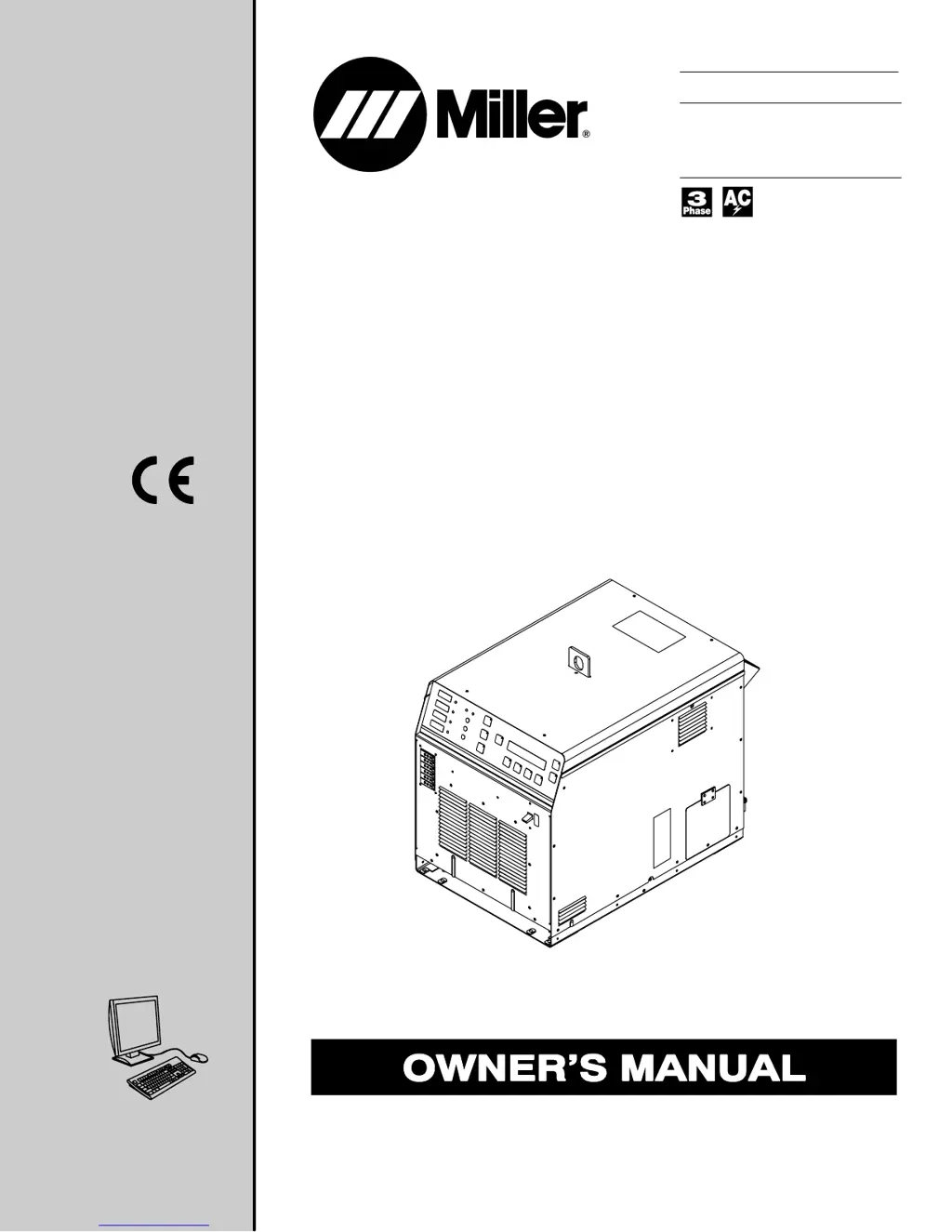
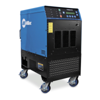
ProHeat 35
Processes
Description
Induction Heating Power Source
Induction Heating
OM-222 166K 200711
File: Induction Heating
Visit our website at
www.MillerWelds.com

Table of Contents

Questions and Answers

  • B
    briana91Sep 8, 2025
    How to resolve Output Voltage Limit (L08) on Miller Electric ProHeat 35?
    • M
      Marc Valentine Jr.Sep 8, 2025
      To resolve an Output Voltage Limit (L08) on your Miller Electric Welding System, increase the number of turns, increase the coil space, shorten the extension cable, and increase the insulation width.
  • J
    jefferymartinezAug 23, 2025
    What to do if I see a Coolant Overtemp Fault (F69) on my Miller Electric ProHeat 35 Welding System?
    • M
      Marissa JohnstonAug 23, 2025
      To troubleshoot a Coolant Overtemp Fault (F69) in your Miller Electric Welding System, check the coolant flow and level. Clean the coolant filters and heat exchanger. Also, increase the number of turns and verify that the insulation thickness is appropriate.
  • A
    Alyssa BellAug 25, 2025
    What to do if my Miller Electric Welding System is showing a Coolant Flow Fault (F61)?
    • M
      Mary HaynesAug 25, 2025
      If your Miller Electric Welding System displays a Coolant Flow Fault (F61), you should check for coolant leaks and blockages. Clean the coolant filter, verify the coolant level, and check the coolant connections.
  • C
    caitlin40Aug 27, 2025
    What should I do if my Miller Electric Welding System displays a Cable Connection Fault (F68)?
    • M
      Matthew DiazAug 27, 2025
      If you encounter a Cable Connection Fault (F68) with your Miller Electric Welding System, check for loose or open output connections. Make sure all output cables are of the same type and verify the receptacle plug is properly connected.
  • J
    James ParksAug 27, 2025
    What should I do if my Miller Electric Welding System is showing a Coolant Overtemp Limit (L11)?
    • M
      Mary RobinsonAug 28, 2025
      If your Miller Electric Welding System shows a Coolant Overtemp Limit (L11), check the coolant flow and level. Clean the coolant filters and heat exchanger. Increase the number of turns and verify the appropriate insulation thickness.
  • J
    jkellySep 22, 2025
    What to do for Thermocouple #1 Open (L01) on Miller Electric ProHeat 35 Welding System?
    • S
      sraySep 22, 2025
      To address Thermocouple #1 Open (L01) on your Miller Electric Welding System, check for an open temperature sensor and repair it. Alternatively, change to a back-up temperature sensor.
  • D
    Dr. Christopher JohnsonSep 16, 2025
    What to do for Thermocouple #3 Open (L03) on Miller Electric ProHeat 35 Welding System?
    • P
      Pamela AlexanderSep 16, 2025
      To address Thermocouple #3 Open (L03) on your Miller Electric Welding System, check for an open temperature sensor and repair it. Alternatively, change to a back-up temperature sensor.
  • B
    Brittany SnowSep 18, 2025
    What to do for Themocouple #2 Open (L02) on Miller Electric ProHeat 35?
    • L
      Larry LiuSep 18, 2025
      To address Thermocouple #2 Open (L02) on your Miller Electric Welding System, check for an open temperature sensor and repair it. Alternatively, change to a back-up temperature sensor.
  • C
    Cassandra MillerSep 7, 2025
    What to do for Output Current Limit (L09) on Miller Electric ProHeat 35?
    • K
      Kayla TrujilloSep 7, 2025
      To address an Output Current Limit (L09) on your Miller Electric Welding System, tighten the blanket against the pipe surface.
  • R
    Ruben GarrettSep 4, 2025
    What should I do if my Miller Electric ProHeat 35 shows a Line Voltage Fault (F63)?
    • C
      christopher65Sep 4, 2025
      If you are experiencing a Line Voltage Fault (F63) with your Miller Electric Welding System, check the line voltage.

Summary

SECTION 1 - SAFETY PRECAUTIONS - READ BEFORE USING

Symbol Usage

Explains symbols used in the manual for safety warnings.

Fire, Burn, and Radiation Hazards

Details hazards from fire, explosion, burns, and HF radiation.

Induction Heating Hazards

Details hazards associated with induction heating operations.

Electrical and Environmental Hazards

Covers electric shock, DC voltage, fumes, gases, fire, and explosion hazards.

SECTION 4 - INSTALLATION

Electrical Service Guide

Provides guidance on electrical service requirements and circuit protection.

Connecting 3-Phase Input Power (460;575 V)

Details the procedure for connecting 3-phase input power for 460/575V models.

Connecting 3-Phase Input Power (400;460 V)

Details the procedure for connecting 3-phase input power for 400/460V models.

SECTION 5 - COMPONENTS AND CONTROLS

SECTION 6 - SETUP AND OPERATION

Programming Overview

Explains how to program heating cycles using temperature-based control.

Bake-Out and PWHT Processes

Explains Bake-Out and PWHT processes for temperature programming.

Custom Program Creation

Guides the creation of custom heating programs with multiple steps.

Custom Program Segments

Explains different segment types (Step, Ramp, Soak, End) for custom program creation.

Manual Control

Explains the Manual Control mode for setting a specific power level for a duration.

System Setup

Guides the user through configuring the system settings via the setup screen.

Preheat Process

Describes the Preheat process for simple heating and holding temperature.

SECTION 7 - MAINTENANCE

SECTION 8 - SAFETY PRECAUTIONS FOR SERVICING

Servicing Safety Symbols and Hazards

Explains servicing symbols and details hazards like electric shock and hot parts.

Servicing Hazards (Moving Parts, Fields, Radiation, Overheating)

Covers hazards from moving parts, magnetic fields, radiation, and overheating.

SECTION 9 - DIAGNOSTICS & TROUBLESHOOTING

Limit Conditions and Codes

Describes limit conditions, their indicators, and specific codes with solutions.

Fault Conditions and Codes

Explains fault conditions, their indicators, and specific codes with required actions.

SECTION 10 - ELECTRICAL DIAGRAM

Limited Warranty

Miller Electric ProHeat 35 Specifications

General IconGeneral
Input Voltage208 - 575 V
Weight41 lb (18.6 kg)
Dimensions18.5 in x 12.5 in x 10.5 in (470 mm x 318 mm x 267 mm)
Input Frequency50/60 Hz
Cooling MethodAir-cooled
Duty Cycle100%

Related product manuals