19
SECTION IV
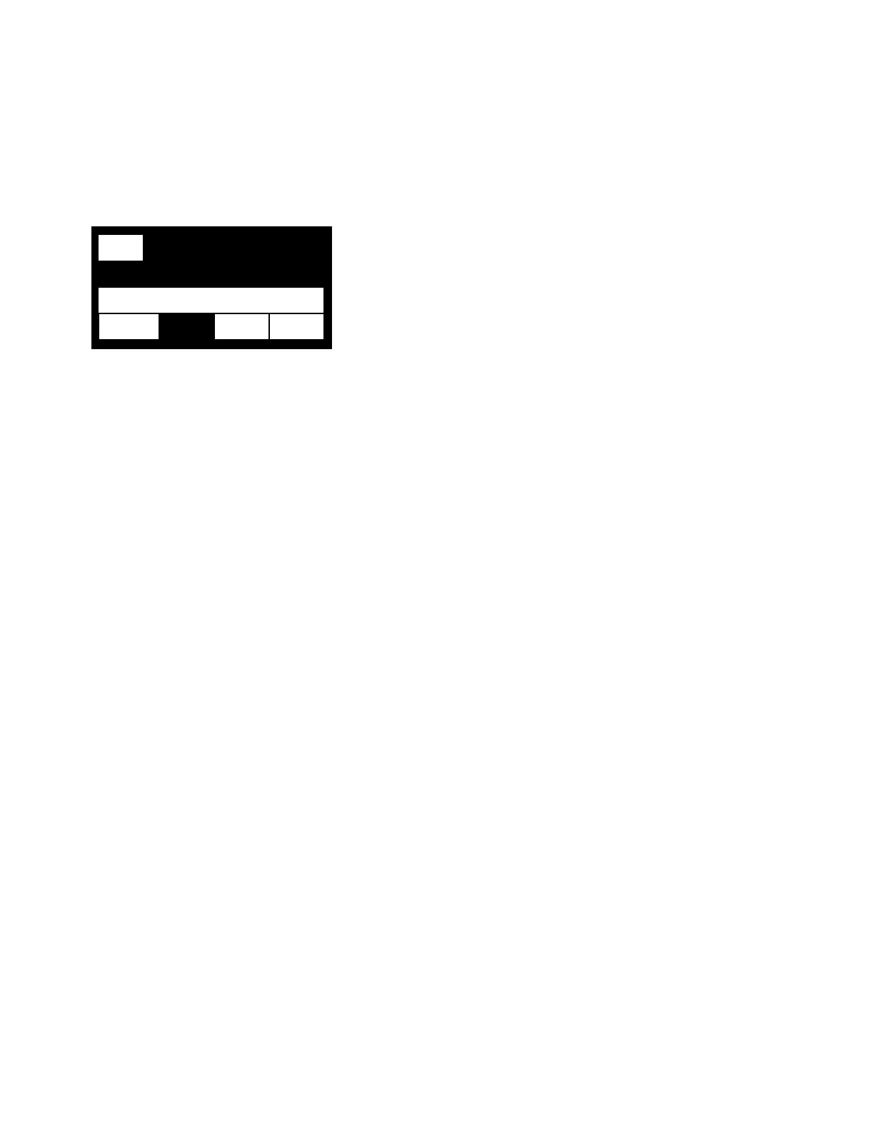
WELD SCREEN
LINE 1
The RUN on the left is highlighted to show that the 9700W is in the run state
LINE 2
The label of the line informs you of the current state of the weld schedule. The states that can be shown are
as follows: START DLY, WELD and STOP DLY. If the number is counting down it is how long that segment of
the weld schedule is left (START DLY and STOP DLY). It will count up in WELD since the 9700W does not
know how long the weld segment will be.
LINE 3
This line shows the actual or the programmed wire feed speed as set in the Calibration menu. If the line is
highlighted that means that the speed can be changed by using the dial. If the wire feed speed is changed,
the new speed will be used for the next weld, but will not be saved to permanent memory unless it is saved
after the weld is finished. To save go back to program menu and press the left arrow button.
LINE 4
This line shows that status of various outputs and inputs. AUX1, AUX2, and AUX3 are highlighted when the
9700W sends out an active signal. If the EXT is highlighted, it means the 9700W has received an external
start command. In this case the STOP button acts like a wire lock command. Pressing the STOP button will
cause the wire to stop feeding and the START button would start the wire again.
RUN
LINE 1
12
LINE 2
LINE 3
AUX2 AUX3 EXT LINE 4