22
SECTION VII
ELECTRICAL INSTALLATION
A. Input Power
The 9700W control is designed to operate on either 115VAC or 230VAC 50/60HZ and is fitted with a 10 amp
circuit breaker suitable for either voltage. The unit is typically configured for your choice of voltage prior to
shipment. The unit ships with a standard 6 foot length cable for 115/120 VAC only input. If it is necessary to
change the input voltage, this can be done as follows:
Make sure no power is apply to unit during this procedure.
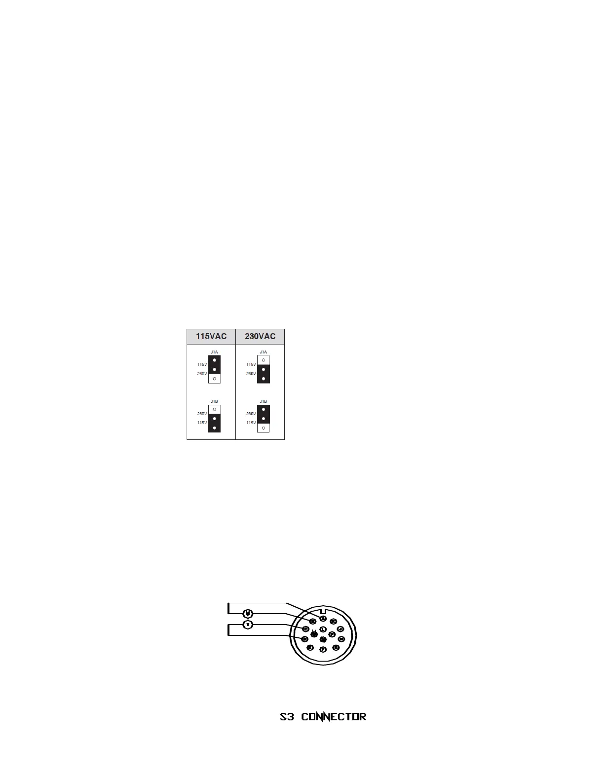
Open the front door of the unit and locate the motor control module (Picture of jumpers on motor drive).
At the top, left hand side of the module there are two jumpers, these are marked J1A and J1B. These
should be set as shown in the diagram below.
Figure 4: Input Voltage change over.
Since the 9700W is fitted with an IEC 60320-1 C14 power receptacle you will need to get a power cord with
an IEC 60320-1 C13 connector rated for 250VAC to use with 220/230VAC.
B. Output Connections
All output connections to and from the 9700W control use Amphenol connectors. There are three
Amphenol connectors, the lower one is marked S1, the center one is S2 and the upper one is S3.
Interconnection of the 9700W control with associated equipment is shown on the following pages.