Do you have a question about the Miller Big Blue 350 PipePro and is the answer not in the manual?
Explains symbols used in the manual for hazard identification.
Details hazards associated with arc welding processes and precautions.
Details hazards related to the engine, including battery, fuel, and moving parts.
Covers hazards associated with hydraulic equipment and fluid.
Outlines dangers related to compressed air equipment and its use.
Explains symbols related to installation, operation, and maintenance.
Provides warnings about chemicals known to cause cancer or birth defects.
Lists key safety standards and their sources for reference.
Discusses electromagnetic fields and their potential interference with medical implants.
Defines various symbols and terms used in the manual.
Provides detailed specifications for welding, power output, and engine.
Lists physical dimensions, weights, and safe operating angles for the unit.
Shows Constant Current (CC) volt-ampere curves for different welding modes.
Illustrates typical fuel consumption based on weld output.
Explains duty cycle limitations to prevent overheating and damage.
Displays the AC generator power output characteristics.
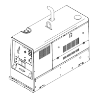
Identifies the location of serial and rating labels on the product.
Provides instructions and safety warnings for installing the welding generator.
Details methods for securely mounting the generator unit.
Explains the process for properly grounding the generator to a vehicle frame.
Guides the installation of the exhaust pipe for the generator.
Provides steps for activating a dry charge battery.
Details the procedure for correctly connecting the battery.
Lists essential checks to perform before starting the engine.
Identifies weld output terminals and their function for different welding modes.
Explains the correct procedure for connecting weld cables to output terminals.
Provides guidelines for selecting appropriate weld cable sizes based on current and length.
Describes how to connect remote controls to the RC14 receptacle.
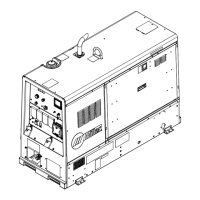
Identifies and illustrates the controls on the front panel of the welding generator.
Provides detailed descriptions of each front panel control and their functions.
Explains the function and applications of the process/contactor switch.
Details the Lift-Arc TIG starting and Auto-Stop features for welding.
Guides on using remote controls for voltage and amperage adjustment.
Explains the functions and display indicators of the fuel/hour gauge.
Instructions for operating the engine block heater for cold weather.
Describes the different power receptacles available on the generator.
Shows the maintenance label and its recommended service intervals.
Outlines a schedule for routine maintenance tasks and their frequency.
Provides instructions for cleaning or replacing the air cleaner element.
Details how to inspect generator brushes for wear.
Guides on inspecting and cleaning the spark arrestor muffler.
Instructions for servicing the engine's cooling system, including coolant levels.
Covers maintenance procedures for the fuel and lubrication systems.
Explains the overload protection devices (breakers, fuses) and their function.
Notes that engine speed adjustment should be done by an authorized service agent.
Describes how to use meter displays for diagnosing faults and troubleshooting.
Provides tips for cleaning and maintaining stainless steel components.
Lists common problems and their remedies for welding and generator output.
Continues troubleshooting for engine issues such as starting or stopping.
Presents the main electrical circuit diagram for the welding generator.
Explains wetstacking and how to prevent it during engine run-in.
Provides steps for running in the engine using a load bank.
Details the procedure for running in the engine using a resistance grid.
Guidance on selecting appropriate equipment, including plugs and cords.
Instructions for grounding the generator to a vehicle frame for safety.
Explains how to ground the generator when supplying power to building systems.
Helps calculate power requirements for various equipment.
Lists power requirements for different types and sizes of industrial motors.
Lists power requirements for common farm and home equipment.
Lists power requirements for various contractor equipment.
Provides data on starting power requirements for single-phase induction motors.
Guides on managing generator output and starting loads.
Illustrates typical connections for supplying standby power from the generator.
Provides tables for selecting extension cords based on current, load, and length.
Shows an exploded view of the main assembly with numbered parts.
Shows the control panel assembly with a list of components.
Illustrates the front panel with its components and parts list.
Shows the generator assembly with a detailed parts list.
Depicts the weld control assembly with its components and parts.
Details Miller's limited warranty terms, coverage, and exclusions.
| Max Output | 400 A |
|---|---|
| Welding Amperage Range | 20 - 400 A |
| Engine Power | 24.8 HP (18.5 kW) |
| Frequency | 60 Hz |
| Type | Engine Driven Welding Generator |
| Rated Output | 350 A at 100% duty cycle |
| Open Circuit Voltage | 80 V |
| Weight | 1448 lb (657 kg) |
| Fuel Capacity | 25 gal (94.6 L) |
| Fuel Tank Capacity | 20 gal (75.7 L) |
| Engine | Diesel |