Do you have a question about the Miller Big Blue 400 CX CE and is the answer not in the manual?
Explains symbols used in the manual for safety warnings.
Details hazards associated with arc welding processes.
Outlines potential dangers related to the engine.
Describes hazards associated with hydraulic systems.
Details risks related to compressed air equipment.
Covers symbols for installation, operation, and maintenance safety.
Lists chemical warnings required by California law.
References key safety standards applicable to welding equipment.
Discusses electromagnetic field information and precautions.
Explains symbols used in the manual for safety warnings.
Details hazards associated with arc welding processes.
Outlines potential dangers related to the engine.
Describes hazards associated with hydraulic systems.
Details risks related to compressed air equipment.
Covers additional dangers for installation, operation, and maintenance.
Lists chemical warnings required by California law.
References key safety standards applicable to welding equipment.
Discusses electromagnetic field information and precautions.
Provides information on CE marked products for the EU market.
Details welding, power, and engine specifications of the unit.
Lists the physical dimensions and weight of the generator.
Shows voltage and amperage output capabilities for different welding modes.
Illustrates typical fuel usage based on weld output.
Explains duty cycle and potential overheating issues.
Shows the generator's AC power output curve in amperes.
Identifies the location of the serial and rating labels on the unit.
Provides guidance on moving and securing the welding generator.
Details methods for mounting the welding generator to a surface or trailer.
Explains how to properly ground the generator to a vehicle frame.
Instructions for installing the exhaust pipe.
Steps for activating a dry charge battery.
Procedure for connecting the unit's battery.
Lists essential checks before starting the engine.
How to connect weld cables to output terminals for various processes.
Guide for choosing appropriate weld cable sizes based on length and amperage.
Details connections for remote controls via the RC14 receptacle.
Overview of the generator's front panel controls.
Detailed explanation of each front panel control's function.
Explains the function and settings of the process/contactor switch.
Describes the Lift-Arc TIG starting and stopping procedures.
How to use remote controls for voltage and amperage adjustment.
Explains the fuel/hour gauge and its display indicators.
Details the types and functions of auxiliary power receptacles.
Explains the maintenance schedule and information found on the unit's label.
Outlines the regular maintenance schedule based on operating hours.
Provides contact information and steps for engine-related service issues.
Instructions for inspecting and checking generator brushes.
Steps for cleaning or replacing the air cleaner element.
Procedure for inspecting and cleaning the spark arrestor muffler.
Guidance on checking and servicing the engine's cooling system.
How to adjust engine speed for optimal performance.
Maintenance procedures for fuel and lubrication systems.
Explains the overload protection devices and their functions.
Interprets help codes displayed on optional meters for diagnostics.
Provides solutions for common welding and generator operational problems.
Explains wetstacking and its causes during engine run-in.
Step-by-step guide for run-in using a load bank.
Procedure for engine run-in using a resistance grid.
Guidance on selecting appropriate equipment for generator connection.
How to properly ground the generator when mounted on a vehicle.
Procedures for grounding the generator when supplying power to building systems.
Explains how to calculate power requirements for various equipment.
Power requirements for different types of industrial motors.
Power needs for common farm and home equipment.
Power requirements for various contractor tools and equipment.
Details starting power requirements for single-phase induction motors.
Guidelines on managing generator load and power supply.
Illustrates typical wiring for standby power applications.
Charts for selecting appropriate extension cords based on load and length.
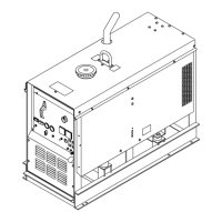
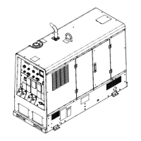
Diagram and list of major components in the main assembly.
Diagram and list of front panel components.
Diagram and list of components on the control panel.
Diagram and list of generator assembly parts.
Diagram and list of rectifier assembly components.
Lists components related to various wiring harnesses.
Contact information and guidance for obtaining service and support.
| Brand | Miller |
|---|---|
| Model | Big Blue 400 CX CE |
| Category | Welding System |
| Language | English |