Do you have a question about the Miller Kubota Big Blue 600 Pro and is the answer not in the manual?
| Model | Big Blue 600 Pro |
|---|---|
| Generator Power | 12, 000 Watts Peak, 10, 000 Watts Continuous |
| Type | Engine-Driven Welding Generator |
| Rated Output | 600A at 40V, 100% Duty Cycle |
| Welding Amperage Range | 30-600A |
| Engine Power | 24.8 HP |
| Output Current Range | 30-600A |
| Open Circuit Voltage | 80 VDC |
| Welding Processes | Stick, TIG, MIG, Flux-Cored |
Explains the meaning and usage of safety symbols found in the manual.
Details hazards associated with arc welding processes and necessary precautions.
Warns about the lethal danger of electric shock from live electrical parts and necessary safety measures.
Alerts users to the risk of burns from hot components and advises allowing cooling time.
Warns about eye injury from flying metal and sparks, recommending safety glasses.
Discusses dangers of inhaling welding fumes and gases and ventilation requirements.
Addresses fire and explosion risks associated with welding operations and preventative measures.
Alerts users to potential hearing damage from equipment noise and the need for ear protection.
Covers potential hazards related to the engine, such as battery explosion and fuel fires.
Outlines dangers associated with compressed air equipment and safe usage practices.
Presents symbols related to installation, operation, and maintenance hazards.
Warns about the risks of lifting and handling heavy equipment to prevent injury.
Discusses potential damage from overheating motors and electrical components.
Alerts users to the danger of flying sparks and the need for protective gear and fire prevention.
Details hazards associated with battery charging, including explosion and chemical burns.
Warns about the dangers of high-pressure fluids, especially fuel injection.
Covers hazards related to handling welding wire, such as accidental trigger activation.
Discusses the risk of overheating equipment due to overuse or blocked airflow.
Lists chemicals in the product known to cause cancer or birth defects in California.
Lists key safety standards and their sources for welding and allied processes.
Explains EMF effects and procedures to minimize exposure, especially for those with medical implants.
Alerts users to potential hearing damage from equipment noise and the need for ear protection.
Discusses EMF interference with medical implants and precautions for wearers.
Highlights the danger of compressed gas cylinder damage and explosion, emphasizing careful handling.
Provides definitions and explanations for additional safety symbols used on CE products.
Explains various symbols used in the manual, covering units, processes, and controls.
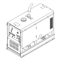
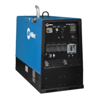
Indicates where to find serial number and rating information on the product.
Lists detailed specifications for welding output, generator power, and engine.
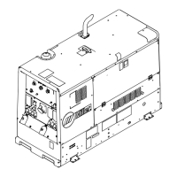
Provides physical dimensions, weight, and acceptable operating angles for the unit.
Details IP rating and storage/operating temperature ranges for the equipment.
Explains duty cycle limitations and the risks of overheating the unit.
Shows typical fuel usage based on weld or power loads.
Presents graphical representations of voltage and amperage output capabilities for different welding modes.
Displays AC power output curves for single-phase and three-phase generator operation.
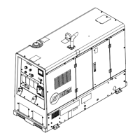
Provides instructions and safety precautions for mounting and securing the welder/generator unit.
Details procedures for grounding the generator frame to a vehicle for safety.
Gives instructions for safely installing the engine exhaust pipe.
Explains the correct procedure and safety precautions for connecting the unit's battery.
Lists essential checks to perform on engine fluids, fuel, and coolant before starting.
Specific guidance on checking engine oil, fuel level, and coolant for proper operation.
Describes how to connect cables to the weld output terminals for different welding processes.
Highlights proper cable connection procedures to prevent overheating and damage.
Provides a guide for choosing appropriate weld cable sizes based on amperage and length.
Explains how to connect remote controls and other devices to the unit's remote receptacle.
Identifies and describes the function of controls on the welder/generator's front panel.
Provides detailed explanations for each front panel control and meter.
Outlines the step-by-step procedure for safely starting the engine.
Explains how to use the switch to select welding processes and control output.
Details how to adjust arc control settings for different welding modes and their effects.
Describes the VRD switch function for reducing open-circuit voltage in Stick mode.
Provides instructions for initiating an arc using the scratch start technique for Stick welding.
Explains the Lift-Arc TIG process and how to use Auto-Stop for arc termination.
Details how to use remote controls for adjusting voltage and amperage in CC and CV welding.
Explains how to use the engine block heater to maintain optimal engine temperature.
Identifies and describes the various auxiliary power receptacles and their ratings.
Explains GFCI protection, how to reset, and how to test GFCI receptacles.
Shows the maintenance schedule and recommended service intervals for the unit.
Provides instructions for cleaning the exterior of the welder/generator.
Outlines the schedule for routine maintenance tasks like checking fluids and filters.
Details the procedure for cleaning or replacing the air cleaner element.
Explains how to inspect generator brushes for wear and when to replace them.
Provides instructions on how to safely replace the unit's battery.
Offers guidance on maintaining lead-acid batteries, including recharging.
Advises against tampering with engine ECU and recommends contacting service for adjustments.
Lists recommended oil types and viscosity charts for engine lubrication.
Guides on replacing fuel filters, changing oil, and draining fuel tank sludge.
Identifies various protectors and circuit breakers for engine and generator overload protection.
Explains how to interpret help codes displayed on the voltmeter/ammeter for troubleshooting.
Provides a systematic guide to diagnosing and resolving common welding issues.
Details common problems related to generator power output and their remedies.
Lists common engine-related troubles and their corresponding solutions.
Lists recommended spare parts for the unit, including part numbers and descriptions.
Identifies the components of the engine information display and their functions.
Explains the purpose and usage of the navigation and function buttons for the display.
Describes the 'RPM Signal Failed' message and how to reset it.
Details the 'Wait to Start/Preheating' and 'Service Reminder' displays and their meanings.
Explains the default 6-up display configuration showing engine parameters.
Guides on navigating from the 6-up display to specific 1-up displays, like oil pressure.
Shows various single-parameter displays for machine hours, coolant temp, fuel level, etc.
Explains the fuel level indicators and warnings displayed on the unit.
Describes warning and shutdown indicators and how to acknowledge faults.
Explains how to access and interpret engine diagnostic codes (SPN/FMI).
Details how to access the main menu using the factory set access code.
Guides on resetting service reminders for oil changes through the main menu.
Explains how to adjust display settings like brightness, contrast, and units.
Describes how to view and modify service reminder intervals for engine and compressor.
Covers access to OEM options, version info, stored codes, and language settings.
Explains what wetstacking is and the conditions that cause it.
Details the process for running in the engine using load banks or resistance grids.
Provides guidance on selecting appropriate plugs and equipment for generator power.
Details procedures for grounding the generator frame to a vehicle for safety.
Explains grounding requirements when supplying power to building electrical systems.
Guides on calculating starting amperage requirements for single-phase induction motors.
Discusses generator output limits and rules for connecting loads.
Illustrates typical connections for supplying standby power using the generator.
Provides charts for selecting extension cords based on load, voltage, and length.