EasyManua.ls Logo

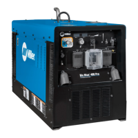
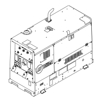
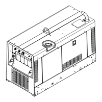
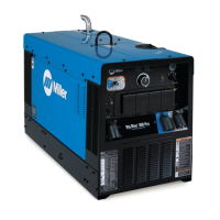
Miller Big Blue 600 Air Pak User Manual

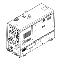
Miller Big Blue 600 Air Pak
114 pages
To Next Page IconTo Next Page
Page #1 background imageLoading...
Page #1 background image
Processes
OM-279640B 201710
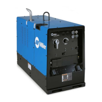
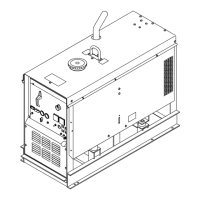
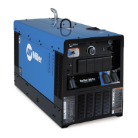
Big Blue 600 Air Pak
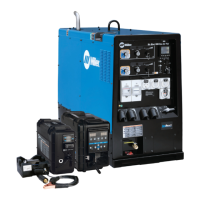
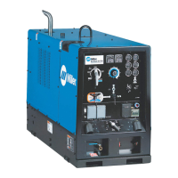
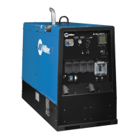
Big Blue 800 Duo Pro
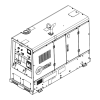
Big Blue 800 Duo Air Pak
Processes
Description
TIG (GTAW) Welding
Stick (SMAW) Welding
Engine Driven Welder/Generator And
Air Compressor
Air Carbon Arc (CAC-A)
Cutting and Gouging
MIG (GMAW) Welding
Flux Cored (FCAW) Welding
)
)
File: Engine Drive
For product information,
Owner’s Manual translations,
and more, visit
www.MillerWelds.com
)
)
)
)

Table of Contents

Questions and Answers:

Miller Big Blue 600 Air Pak Specifications

General IconGeneral
ModelBig Blue 600 Air Pak
Rated Output (Amps)600
Fuel TypeDiesel
Rated Output600 A
Open Circuit Voltage (V)80
Output Voltage120/240 V
Auxiliary Power (V)120/240
Welding ProcessesStick (SMAW), TIG (GTAW), MIG (GMAW), Flux-Cored (FCAW), Air Carbon Arc Cutting (CAC-A)

Summary

From Miller to You

SECTION 1 SAFETY PRECAUTIONS READ BEFORE USING

1-1. Symbol Usage

Explains symbols used for hazards and special instructions.

1-2. Arc Welding Hazards

Details hazards associated with arc welding processes, including shock and equipment safety.

SECTION 1 SAFETY PRECAUTIONS

1-3. Engine Hazards

Covers battery, fuel, moving parts, exhaust, hot parts, and coolant hazards.

1-4. Compressed Air Hazards

Outlines risks associated with compressed air equipment, including injury, inhalation, and pressure hazards.

SECTION 1 SAFETY PRECAUTIONS

1-5. Additional Symbols For Installation, Operation, And Maintenance

Introduces symbols related to fire, falling equipment, overheating, sparks, and moving parts.

SECTION 1 SAFETY PRECAUTIONS

1-6. California Proposition 65 Warnings

Provides warnings regarding chemicals known to cause cancer or birth defects.

1-7. Principal Safety Standards

Lists key safety standards and organizations for reference.

1-8. EMF Information

Explains electromagnetic fields and their potential impact on medical implants.

SECTION 3 DEFINITIONS

3-1. Additional Safety Symbols And Definitions

Defines various safety symbols found on the equipment and in the manual.

SECTION 3 DEFINITIONS

3-2. Miscellaneous Symbols And Definitions

Defines miscellaneous symbols including units of measure and operational states.

SECTION 4 SPECIFICATIONS

4-2. Weld, Power, And Engine Specifications

Provides detailed specifications for welding output, power ratings, and engine performance.

4-3. Air Compressor Specifications (Air Pak Models)

Lists specifications for the air compressor system on Air Pak models.

4-5. Dimensions, Weights, And Operating Angles

Presents physical dimensions, weight, and safe operating tilt angles for the unit.

4-6. Duty Cycle And Overheating

Explains duty cycle ratings and the risks of overheating the equipment.

SECTION 4 SPECIFICATIONS

4-7. Volt-Ampere Curves (800 Models)

Illustrates voltage and amperage output capabilities for 800 models across different welding processes.

SECTION 4 SPECIFICATIONS

4-8. Volt-Ampere Curves (600 Models)

Shows voltage and amperage output capabilities for 600 models across different welding processes.

SECTION 4 SPECIFICATIONS

4-9. AC Generator Power Curves

Displays AC generator power output curves for single and three-phase configurations.

SECTION 4 SPECIFICATIONS

4-10. Fuel Consumption

Provides graphs showing typical fuel consumption based on weld output and operating modes.

SECTION 5 INSTALLATION

5-1. Installing Welder/Generator

Details procedures for safely installing the welder/generator, including movement and mounting.

SECTION 5 INSTALLATION

5-2. Grounding Generator To Truck Or Trailer Frame

Explains the importance and method of grounding the generator to a vehicle frame.

5-3. Installing Exhaust Pipe

Provides instructions for installing the exhaust pipe, emphasizing safety and direction.

SECTION 5 INSTALLATION

5-4. Connecting The Battery

Outlines the procedure for connecting the unit's battery, including safety precautions.

5-5. Using The Battery Disconnect Switch

Describes the function and operation of the battery disconnect switch.

SECTION 5 INSTALLATION

5-6. Engine Prestart Checks

Lists essential checks to perform before starting the engine, covering fluids, fuel, and oil.

SECTION 5 INSTALLATION

5-7. Connecting To Weld Output Terminals

Details the correct procedure for connecting weld cables to the output terminals to prevent hazards.

SECTION 5 INSTALLATION

5-8. Making Dual Operator CC Weld Connections w/ Separate Work Cables (800 Models)

Explains how to connect cables for dual operator CC welding with separate work cables.

SECTION 5 INSTALLATION

5-9. Making Dual Operator Mode CC Weld Connections w/ Common Work Cable (800 Models)

Details the process for dual operator CC welding using a common work cable.

SECTION 5 INSTALLATION

5-10. Making Dual Operator CV Weld Connections w/ Separate Work Cables (800 Models)

Provides instructions for dual operator CV welding with separate work cables.

SECTION 5 INSTALLATION

5-11. Making Dual Operator CV Weld Connections w/ Common Work Cable (800 Models)

Details dual operator CV welding connections using a common work cable.

5-12. Making Dual Operator CC And CV Weld Connections w/ Separate Work Cables (800 Models)

Explains dual operator CC and CV welding connections with separate work cables.

SECTION 5 INSTALLATION

5-13. Making Dual Operator CC And CV Weld Connections w/ Common Work Cable (800 Models)

Details dual operator CC and CV welding connections using a common work cable.

5-14. Making Single Operator CC Weld Connections (800 Models)

Describes how to establish single operator CC weld connections for 800 models.

SECTION 5 INSTALLATION

5-15. Selecting Cable Sizes*

Provides a chart to help select appropriate weld cable sizes based on amperage and length.

5-16. Weld Output Terminals

Identifies the location and type of weld output terminals on the unit.

SECTION 5 INSTALLATION

5-17. Connecting To The Air Compressor (Air Pak Models)

Explains how to connect the air compressor, including safety and operational notes.

SECTION 6 OPERATING WELDER/GENERATOR

6-1. Front Panel Controls (See Section 6-2)

Provides an overview and labels for the controls on the front panel of the welder/generator.

SECTION 6 OPERATING WELDER/GENERATOR

6-2. Description Of Front Panel Controls (See Section 6-1)

Details the function of each control and indicator on the front panel of the welder/generator.

SECTION 6 OPERATING WELDER/GENERATOR

6-3. Engine Starting Sequence

Outlines the steps and displays involved in starting the engine, including preheating.

SECTION 6 OPERATING WELDER/GENERATOR

6-4. Process/Contactor Switch

Explains how to use the Process/Contactor switch to select welding processes and control output.

SECTION 6 OPERATING WELDER/GENERATOR

6-5. Service Menu

Describes how to access and navigate the service menu for adjusting settings like Hot Start and Auto Crater.

6-6. Arc Control Settings

Details how to adjust arc control for different welding processes to optimize arc characteristics.

SECTION 6 OPERATING WELDER/GENERATOR

6-7. Stick Start Procedure Scratch Start Technique

Explains the scratch start technique for initiating an arc when using stick welding.

6-8. Lift-Arc TIG With Auto-Stop And Auto-Crater

Describes the Lift-Arc TIG starting method and the Auto-Stop/Auto-Crater features.

SECTION 6 OPERATING WELDER/GENERATOR

6-9. Voltage/Amperage Control With 14-Pin Remote Accessory

Explains how to use a remote accessory for voltage and amperage control.

SECTION 6 OPERATING WELDER/GENERATOR

6-10. Engine Block Heater Operation

Details the operation of the engine block heater for maintaining coolant temperature.

SECTION 6 OPERATING WELDER/GENERATOR

6-11. Updating Software

Provides instructions for updating the machine's software using a USB flash drive.

SECTION 6 OPERATING WELDER/GENERATOR

6-12. Summary File

Explains how to access summary files saved to a USB stick for diagnostic and weld information.

SECTION 6 OPERATING WELDER/GENERATOR

6-13. Associating ArcReach Devices (ArcReach Models Only)

Describes how to associate ArcReach accessories with the welder/generator.

SECTION 6 OPERATING WELDER/GENERATOR

6-14. Optional Air Dryer Operation (Air Pak Models)

Explains the operation of the optional air dryer system, including circuit breaker reset.

SECTION 7 OPERATING AUXILIARY EQUIPMENT

7-1. North American Auxiliary Power Receptacles

Identifies and describes the various auxiliary power receptacles and their protective circuits.

SECTION 7 OPERATING AUXILIARY EQUIPMENT

7-2. GFCI Receptacle Information, Resetting, And Testing

Provides information on GFCI receptacles, including how to reset and test them for safety.

SECTION 8 MAINTENANCE

8-1. Maintenance Label

Indicates the location of the maintenance label with service intervals and specifications.

SECTION 8 MAINTENANCE

8-2. Cleaning Unit

Details how to clean the exterior of the unit to prevent rust and maintain appearance.

8-3. Routine Maintenance

Outlines a schedule of routine maintenance tasks for the engine and generator based on operating hours.

SECTION 8 MAINTENANCE

8-4. Checking Generator Brushes

Explains how to check generator brush length and when to replace them.

8-5. Battery Replacement

Provides steps for replacing the unit's battery, including safety precautions.

SECTION 8 MAINTENANCE

8-6. Servicing Air Cleaner

Details the procedure for cleaning or replacing the air cleaner element.

SECTION 8 MAINTENANCE

8-7. Battery Maintenance

Offers guidance on battery maintenance, including charging intervals.

8-8. Engine Speed Adjustment

Notes that engine speed is controlled by the ECU and advises contacting a service agent for adjustments.

8-9. Oil Specifications

Lists recommended engine oils and viscosity grades for various temperature conditions.

SECTION 8 MAINTENANCE

8-10. Servicing Fuel And Lubrication Systems

Covers procedures for servicing fuel filters, oil, and the fuel tank, including safety warnings.

SECTION 8 MAINTENANCE

8-11. Engine/Generator Overload Protection

Identifies supplementary protectors and circuit breakers for engine and generator overload protection.

SECTION 8 MAINTENANCE

8-12. Voltmeter/Ammeter Error Displays

Lists common error codes displayed on the voltmeter/ammeter and their potential causes and remedies.

SECTION 8 MAINTENANCE

8-13. Removing Optional Air Dryer For Service

Provides instructions for removing the air dryer assembly to access the battery.

SECTION 9 AIR COMPRESSOR MAINTENANCE (AIR PAK MODELS)

9-1. Air Compressor Maintenance Label

Indicates the location of the maintenance label for the air compressor with service intervals.

SECTION 9 AIR COMPRESSOR MAINTENANCE (AIR PAK MODELS)

9-2. Routine Air Compressor Maintenance

Outlines routine maintenance tasks for the air compressor based on operating hours.

SECTION 9 AIR COMPRESSOR MAINTENANCE (AIR PAK MODELS)

9-3. Servicing Air Cleaner

Details the procedure for cleaning or replacing the air cleaner element for the compressor.

SECTION 9 AIR COMPRESSOR MAINTENANCE (AIR PAK MODELS)

9-4. Compressor Overload Protection

Identifies the circuit breaker that protects the air compressor clutch from overload.

SECTION 9 AIR COMPRESSOR MAINTENANCE (AIR PAK MODELS)

9-5. Servicing Air Compressor

Covers changing compressor oil and filter, and replacing the air/oil separator.

SECTION 9 AIR COMPRESSOR MAINTENANCE (AIR PAK MODELS)

9-6. Adjusting Compressor Air Pressure

Explains how to check and adjust the compressor air pressure, noting limitations.

SECTION 10 TROUBLESHOOTING

10-1. Troubleshooting

A comprehensive guide to diagnosing and resolving common issues with the welder/generator and its components.

SECTION 11 PARTS LIST

11-1. Recommended Spare Parts

Lists recommended spare parts for maintenance and repair, including part numbers and quantities.

SECTION 12 ELECTRICAL DIAGRAMS

Figure 12-1. Circuit Diagram For Big Blue 800 Duo Air Pak Units Part 1

Presents the first part of the electrical circuit diagram for the Big Blue 800 Duo Air Pak.

SECTION 12 ELECTRICAL DIAGRAMS

Figure 12-2. Circuit Diagram For Big Blue 800 Duo Air Pak Units Part 2

Shows the second part of the electrical circuit diagram for the Big Blue 800 Duo Air Pak.

SECTION 12 ELECTRICAL DIAGRAMS

Figure 12-3. Circuit Diagram For Big Blue 600 Air Pak Units Part 1

Presents the first part of the electrical circuit diagram for the Big Blue 600 Air Pak.

SECTION 12 ELECTRICAL DIAGRAMS

Figure 12-4. Circuit Diagram For Big Blue 600 Air Pak Units Part 2

Presents the second part of the electrical circuit diagram for the Big Blue 600 Air Pak.

SECTION 13 ENGINE INFORMATION DISPLAY

13-1. Display Layout And Controls

Identifies the components and layout of the engine information display and its control buttons.

13-2. Function Buttons

Explains the functions of the navigation buttons used to interact with the engine display menus.

SECTION 13 ENGINE INFORMATION DISPLAY

13-3. RPM Signal Failed Display

Describes the display message and conditions for an RPM signal failure.

13-4. Service Reminder Screen

Details the service reminder display for engine maintenance intervals and diagnostic access.

SECTION 13 ENGINE INFORMATION DISPLAY

13-5. 6-Up Display

Explains the default 6-Up display showing multiple engine parameters simultaneously.

13-6. Getting To 1-Up Display

Guides on how to switch from the 6-Up display to a single parameter 1-Up display.

SECTION 13 ENGINE INFORMATION DISPLAY

13-7. 1-Up Displays

Shows various single-parameter 1-Up displays for engine hours, coolant temp, fuel level, etc.

SECTION 13 ENGINE INFORMATION DISPLAY

13-8. 1-Up Compressor Displays

Illustrates the 1-Up display format for compressor-specific information like pressure and hours.

SECTION 13 ENGINE INFORMATION DISPLAY

13-9. Fuel Level Warnings

Explains the fuel level indicators and warnings, including low fuel and no fuel states.

SECTION 13 ENGINE INFORMATION DISPLAY

13-10. Warning or Shutdown Display

Describes how warning and shutdown messages are displayed, including fault indicators and codes.

SECTION 13 ENGINE INFORMATION DISPLAY

Table 13-1. Fault Descriptions

Provides a list of common fault codes (SPN/FMI) and their descriptions for engine issues.

13-11. Engine Diagnostic Display

Explains the engine diagnostic display used by service agents, including SPN/FMI codes.

SECTION 13 ENGINE INFORMATION DISPLAY

13-12. Main Menu Access Code

Details the procedure for accessing the main menu using a factory set access code.

13-13. Main Menu Options Resetting Hours At Oil Change

Guides on resetting service reminders for engine oil and compressor oil after maintenance.

SECTION 13 ENGINE INFORMATION DISPLAY

13-14. Main Menu Options: Brightness, Contrast, And Units

Explains how to adjust display settings like brightness, contrast, and units.

SECTION 13 ENGINE INFORMATION DISPLAY

13-15. Main Menu Options Reminders

Describes how to view, modify, and reset service reminders for engine and compressor.

SECTION 13 ENGINE INFORMATION DISPLAY

13-16. Main Menu Options OEM, Version, Stored Codes, And Language

Covers access to OEM settings, version information, stored fault codes, and language selection.

SECTION 14 RUN-IN PROCEDURE

14-1. Wetstacking

Explains wetstacking in diesel engines and its prevention during the run-in period.

SECTION 14 RUN-IN PROCEDURE

14-2. Run-In Procedure Using Load Bank Or Resistance Grid

Details the procedure for running in the engine using a load bank or resistance grid.

SECTION 15 AIR COMPRESSOR TABLES

15-1. Flow Of Free Air (CFM) Through Orifices Of Various Diameters

Provides a table showing airflow rates through different orifice sizes at various pressures.

SECTION 15 AIR COMPRESSOR TABLES

15-2. Approximate Air Consumption (Cubic Feet) To Operate Pneumatic Equipment At 70-90 P.S.I.G.

Lists approximate air consumption for various pneumatic tools and equipment.

SECTION 16 GENERATOR POWER GUIDELINES

16-1. Selecting Equipment

Provides guidance on selecting appropriate auxiliary equipment for connection to the generator.

16-2. Grounding Generator To Truck Or Trailer Frame

Details the proper grounding procedures for the generator when mounted on a vehicle.

SECTION 16 GENERATOR POWER GUIDELINES

16-3. Grounding When Supplying Building Systems

Explains how to properly ground the generator when supplying power to building systems.

16-4. How Much Power Does Equipment Require?

Discusses power requirements for resistive and non-resistive loads, including starting surge.

SECTION 16 GENERATOR POWER GUIDELINES

16-5. Approximate Power Requirements For Industrial Motors

Lists approximate starting and running watts required for various industrial motors.

16-6. Approximate Power Requirements For Farm/Home Equipment

Provides power requirements for common farm and home equipment, including motors.

SECTION 16 GENERATOR POWER GUIDELINES

16-7. Approximate Power Requirements For Contractor Equipment

Lists power requirements for various contractor tools and equipment.

SECTION 16 GENERATOR POWER GUIDELINES

16-8. Power Required To Start Motor

Explains how to determine the starting amperage needed for single-phase induction motors.

16-9. How Much Power Can Generator Supply?

Discusses generator capacity limits and starting non-resistive loads.

SECTION 16 GENERATOR POWER GUIDELINES

16-10. Typical Connections To Supply Standby Power

Illustrates typical connections for supplying standby power from the generator to a building system.

SECTION 16 GENERATOR POWER GUIDELINES

16-11. Selecting Extension Cord (Use Shortest Cord Possible)

Provides charts for selecting appropriate extension cord lengths based on current, voltage, and conductor size.

True Blue Warranty

Owner's Record

Related product manuals