EasyManua.ls Logo

Miller Big Blue 450 Duo CST User Manual

Miller Big Blue 450 Duo CST
76 pages
To Next Page IconTo Next Page
Page #1 background imageLoading...
Page #1 background image
Processes
OM-247 969M
20120404
Big Blue 450 Duo CST
Big Blue 450X Duo CST
Processes
Description
TIG (GTAW) Welding
Stick (SMAW) Welding
Engine Driven Welding Generator
Visit our website at
www.MillerWelds.com
File: Engine Drive

Table of Contents

Question and Answer IconNeed help?

Do you have a question about the Miller Big Blue 450 Duo CST and is the answer not in the manual?

Miller Big Blue 450 Duo CST Specifications

General IconGeneral
BrandMiller
ModelBig Blue 450 Duo CST
CategoryWelding System
LanguageEnglish

Summary

SECTION 1 - SAFETY PRECAUTIONS - READ BEFORE USING

1-1. Symbol Usage

Explains hazard symbols and their meanings.

1-2. Arc Welding Hazards

Details risks associated with arc welding, including electric shock.

1-3. Engine Hazards

Covers potential dangers related to the engine, fuel, and moving parts.

SECTION 3 – DEFINITIONS

3-1. Wordless Label Definitions

Explains pictorial safety labels found on the equipment.

3-2. Warning Label Definitions

Defines various warning labels and their meanings.

3-3. Symbols And Definitions

Lists and defines symbols used in the manual and on the equipment.

SECTION 4 – SPECIFICATIONS

4-1. Weld, Power, And Engine Specifications

Details electrical output, auxiliary power, and engine data.

4-2. Dimensions, Weights, And Operating Angles

Provides physical measurements and tilt angle limitations.

4-3. Duty Cycle

Explains the percentage of time the unit can operate at rated load.

SECTION 5 - INSTALLATION

5-1. Serial Number And Rating Label Locations

Identifies the location of important identification labels.

5-2. Installing Welding Generator

Covers general guidelines for mounting and placement.

5-3. Mounting Welding Generator

Provides specific instructions for securely mounting the generator.

SECTION 6 – OPERATION

6-1. Front Panel Engine Controls (See Section 6-2)

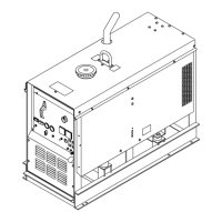
Identifies engine controls on the front panel.

6-2. Description Of Front Panel Engine Controls (See Section 6-1)

Explains the function of each engine control.

6-5. Front Panel CST Controls

Details the controls for the CST (Constant Current) welding function.

SECTION 7 – OPERATING AUXILIARY EQUIPMENT

7-1. Generator Power Receptacles

Details the available power outlets and their usage.

7-2. Export Auxiliary Power Receptacles

Describes auxiliary power outlets for export models.

7-3. GFCI Receptacle Information, Resetting And Testing

Provides guidance on GFCI safety, resetting, and testing.

SECTION 8 – MAINTENANCE & TROUBLESHOOTING

8-1. Maintenance Label

Explains the maintenance schedule indicators and requirements.

8-2. Routine Maintenance

Outlines regular maintenance tasks based on operating hours.

8-3. Cleaning Unit

Instructions for cleaning the exterior of the unit.

SECTION 8 – MAINTENANCE & TROUBLESHOOTING (Continued)

8-4. Servicing Air Cleaner

Steps for cleaning or replacing the air cleaner element.

8-5. Checking Generator Brushes

Procedure for inspecting generator brushes.

8-6. Inspecting And Cleaning Spark Arrestor Muffler

How to inspect and clean the spark arrestor muffler.

SECTION 8 – MAINTENANCE & TROUBLESHOOTING (Continued)

8-7. Servicing Engine Cooling System

Guide for checking and maintaining the engine cooling system.

8-8. Servicing Fuel And Lubrication Systems

Steps for maintaining fuel and oil systems, including filter changes.

SECTION 8 – MAINTENANCE & TROUBLESHOOTING (Continued)

8-9. Overload Protection

Details on fuses, protectors, and circuit breakers for overload protection.

8-10. Adjusting Engine Speed

Information on engine speed adjustment and its limitations.

SECTION 8 – MAINTENANCE & TROUBLESHOOTING (Continued)

8-11. Troubleshooting CST

Guide to diagnosing and resolving issues with the CST system using LED indicators.

SECTION 8 – MAINTENANCE & TROUBLESHOOTING (Continued)

8-12. Troubleshooting Generator

Troubleshooting steps for generator power output issues.

SECTION 9 – ELECTRICAL DIAGRAMS

SECTION 10 - RUN-IN PROCEDURE

10-1. Wetstacking

Explanation of wetstacking and its causes during engine run-in.

10-2. Run-In Procedure Using Load Bank

Step-by-step guide for running in the generator using a load bank.

SECTION 11 – GENERATOR POWER GUIDELINES

11-1. Selecting Equipment

Guidance on selecting compatible electrical equipment for the generator.

11-2. Grounding Generator To Truck Or Trailer Frame

Instructions for safely grounding the generator to a vehicle frame.

11-3. Grounding When Supplying Building Systems

Steps for grounding the generator when connecting to building electrical systems.

SECTION 11 – GENERATOR POWER GUIDELINES (Continued)

11-4. How Much Power Does Equipment Require?

Explains how to calculate power requirements for various equipment.

11-5. Approximate Power Requirements For Industrial Motors

Table showing power needs for industrial motors.

11-6. Approximate Power Requirements For Farm/Home Equipment

Table detailing power requirements for farm and home equipment.

SECTION 11 – GENERATOR POWER GUIDELINES (Continued)

11-7. Approximate Power Requirements For Contractor Equipment

Table listing power needs for contractor equipment.

11-8. Power Required To Start Motor

How to determine the starting power needed for single-phase motors.

11-9. How Much Power Can Generator Supply?

Guidelines on generator power output limits and motor starting rules.

SECTION 11 – GENERATOR POWER GUIDELINES (Continued)

11-10. Typical Connections To Supply Standby Power

Diagrams for connecting the generator for standby power.

11-11. Selecting Extension Cord (Use Shortest Cord Possible)

Charts to help select appropriate extension cords based on load and length.

SECTION 12 - PARTS LIST

Figure 12-1. Main Assembly

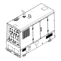
Exploded view of the main assembly components.

Figure 12-2. Panel, Front w/Components

Exploded view of the front panel and its components.

Figure 12-3. Panel, Front w/Components Export

Exploded view of the front panel for export models.

Figure 12-4. Control Panel

Exploded view of the control panel and its components.

Figure 12-5. Generator

Exploded view of the generator components.

WARRANTY

Owner's Record

For Service

Information on contacting distributors or service agencies for assistance.

Related product manuals