Do you have a question about the Miller BOBCAT 225G PLUS and is the answer not in the manual?
A welcoming message from the manufacturer detailing company history and commitment to quality.
Overview of Miller's comprehensive warranty program.
Explains safety symbols and the meaning of various hazard warnings in the manual.
Details risks like electric shock, noise, and fumes during welding.
Covers risks related to fuel, exhaust gases, moving parts, and battery safety.
Additional risks during setup, use, and upkeep, including electrical and mechanical dangers.
Lists key safety standards and codes relevant to welding operations.
Discusses the effects of low frequency electric and magnetic fields on biological systems.
Explains the meaning of various symbols and icons used throughout the manual.
Guidance on proper placement, airflow clearance, and grounding procedures.
Provides physical specifications and limits for operating angles to prevent damage.
Details fuel usage rates for different operating modes and loads.
Essential checks, including fluid levels, before starting the engine.
Step-by-step instructions for correctly connecting the battery terminals.
Guide to connecting weld output terminals and selecting appropriate cable sizes.
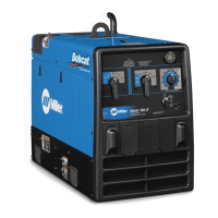
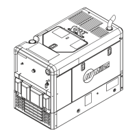
Explains the function of each control knob, switch, and meter on the front panel.
Information on unit's operational duty cycle limits to prevent overheating.
Details on built-in 120V and 240V power outlets and their circuit breakers.
Information on available optional power outlet configurations.
Instructions for wiring an optional 240V plug for different load configurations.
Periodic maintenance tasks and recommended intervals for the equipment.
Explanation of the details provided on the engine maintenance label.
Step-by-step guide for cleaning and maintaining the air cleaner element.
Procedure for changing engine oil, oil filter, and fuel filter.
How to set idle speed and weld/power speed using adjustment controls.
Details on fuses F1 and F6 that protect against electrical overloads.
Instructions for cleaning and inspecting the spark arrestor screen.
Solutions for common welding, auxiliary power, and engine operational issues.
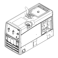
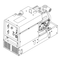
List of parts for the main assembly with diagrams and part numbers.
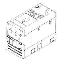
Parts breakdown for the front panel, including switches, meters, and receptacles.
List of parts for the generator assembly, including rotor, stator, and brushes.
| Brand | Miller |
|---|---|
| Model | BOBCAT 225G PLUS |
| Category | Welding System |
| Language | English |