EasyManua.ls Logo

Miller Bobcat 3 Phase User Manual

Miller Bobcat 3 Phase
64 pages
To Next Page IconTo Next Page
Page #1 background imageLoading...
Page #1 background image
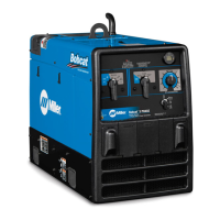
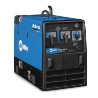
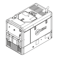
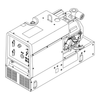
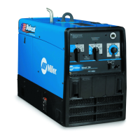
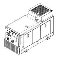
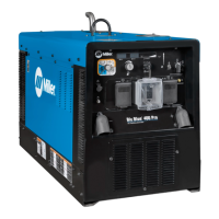
Bobcat 3 Phase
Processes
Description
Non-Critical TIG (GTAW)
Welding
Stick (SMAW) Welding
MIG (GMAW) Welding
Flux Cored (FCAW) Welding
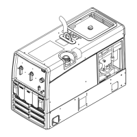
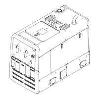
Engine Driven Welding Generator
OM-4436 220 542J
200703
File: Engine Drive
Visit our website at
www.MillerWelds.com

Table of Contents

Questions and Answers:

Miller Bobcat 3 Phase Specifications

General IconGeneral
EngineKohler CH730
Engine Horsepower23 HP
Fuel TypeGasoline
Frequency60 Hz
Input Phase3-Phase
Fuel Tank Capacity12 gallons
Dimensions20 in (508 mm)

Summary

Bobcat 3 Phase

Processes

Lists supported welding processes like Stick, MIG, and Flux Cored.

Description

Identifies the unit as an Engine Driven Welding Generator.

SECTION 1 – SAFETY PRECAUTIONS – READ BEFORE USING

1-1. Symbol Usage

Explains the meaning of warning and safety symbols used throughout the manual.

1-2. Arc Welding Hazards

Covers electric shock, fumes, gases, arc rays, and related safety precautions.

Welding Fire and Explosion Hazards

Warns about fire and explosion risks associated with welding operations and environment.

Hot Parts Burns

Advises caution around hot components to prevent burns during operation or maintenance.

Noise Hearing Damage

Highlights the risk of hearing damage from equipment noise and advises ear protection.

Pacemaker Magnetic Field Warning

Warns pacemaker wearers about magnetic fields and advises consulting a doctor.

Gas Cylinder Explosion Hazard

Details hazards associated with compressed gas cylinders and safe handling practices.

Moving Parts Injury Risk

Warns about injury from moving parts like fans and belts, advising to keep clear.

Fuel Fire and Explosion Risk

Alerts users to fire and explosion risks associated with fuel handling and storage.

Engine Hot Parts Burn Hazard

Advises caution around hot engine parts to prevent burns during operation or maintenance.

Hot Coolant and Steam Burn Hazard

Warns about burns from hot coolant and steam, advising safe checking procedures.

Battery Acid Burn Hazard

Alerts users to the corrosive nature of battery acid and advises protective measures.

Engine Heat Fire Risk

Warns about locating the unit near combustible surfaces due to engine heat.

Engine Exhaust Gas Hazard

Highlights the danger of inhaling engine exhaust gases and advises proper ventilation.

1-4. Compressed Air Hazards

Covers hazards related to compressed air usage, including breathing and injury risks.

Exhaust Sparks Fire Risk

Warns that exhaust sparks can ignite fires and advises using a spark arrestor.

Hot Metal Cutting Explosion Risk

Alerts to fire/explosion risks from hot metal during cutting and gouging.

Hot Compressor Parts Burn Risk

Advises caution around hot compressor or air system parts.

Trapped Air Pressure Hazard

Warns of injury from trapped air pressure and whipping hoses.

Read Instructions and Use Genuine Parts

Emphasizes reading the owner's manual and using genuine replacement parts.

1-5. Additional Symbols

Explains additional symbols related to installation, operation, and maintenance.

Falling Unit Injury Risk

Warns about injury from a falling unit during lifting operations.

Motor Overheating Risk

Alerts to motor damage from overheating due to low voltage or frequency.

Equipment Overuse Overheating Risk

Warns that overuse can cause overheating and damage the equipment.

Flying Sparks Injury Risk

Alerts to injury risk from flying sparks and advises protective gear.

Trailer Tilting Injury Risk

Alerts to injury risk from trailer tilting and advises proper support.

Read Instructions and Use Genuine Parts

Emphasizes using genuine parts and following manual instructions for maintenance.

HF Radiation Interference Risk

Warns about high-frequency radiation interfering with electronic equipment.

1-6. California Proposition 65 Warnings

Provides California Proposition 65 warnings regarding chemicals in fumes and battery components.

1-7. Principal Safety Standards

Lists key safety standards and organizations for welding and allied processes.

1-8. EMF Information

Discusses considerations for welding and low-frequency electric/magnetic fields.

Arc Welding Interference Risk

Details how arc welding can interfere with electronic equipment and how to mitigate it.

Gasoline Engine Prop 65 Warning

California Proposition 65 warning for gasoline engine exhaust.

Diesel Engine Prop 65 Warning

California Proposition 65 warning for diesel engine exhaust.

SECTION 2 – CONSIGNES DE SÉCURITÉ – LIRE AVANT UTILISATION

2-1. Signification des symboles

Explains the meaning of warning and safety symbols used in French safety instructions.

2-2. Dangers relatifs au soudage à l'arc

Covers electric shock, fumes, gases, arc rays, and related safety precautions in French.

Electric Shock Hazard

Warns about fatal electric shock hazards associated with welding equipment.

Fumes and Gases Hazard

Advises on hazards from welding fumes and gases and proper ventilation.

Gas Accumulation Hazard

Warns about the dangers of gas accumulation, especially in confined spaces.

Arc Rays Burn Hazard

Details risks from arc rays causing burns to eyes and skin.

Welding Fire and Explosion Risk

Warns about fire and explosion risks from welding, sparks, and hot materials.

Flying Particles Eye Injury Risk

Alerts to eye injury risk from flying particles during welding, chipping, and grinding.

Hot Parts Burn Hazard

Advises caution around hot parts to prevent severe burns.

Noise Hearing Damage

Warns about hearing damage from noise and recommends ear protection.

Pacemaker Magnetic Field Warning

Advises pacemaker wearers to stay away from magnetic fields.

Gas Cylinder Explosion Hazard

Details explosion hazards from damaged gas cylinders and safe handling.

2-3. Engine Hazards

Covers hazards associated with the engine, including battery, fuel, and moving parts.

Battery Explosion Hazard

Warns about battery explosion hazards and advises safety precautions.

Fuel Fire and Explosion Risk

Alerts to fire and explosion risks associated with fuel.

Moving Parts Injury Risk

Warns about injury from moving engine parts and advises keeping clear.

Hot Engine Parts Burn Hazard

Advises caution around hot engine parts to prevent burns.

Hot Coolant and Steam Burn Hazard

Warns about burns from hot steam and coolant.

Gas Accumulation Hazard

Warns about gas accumulation hazards and proper ventilation.

Battery Acid Burn Hazard

Alerts to battery acid hazards and advises immediate flushing with water.

2-4. Compressed Air Hazards

Covers hazards related to compressed air, including breathing, injury, and pressure.

Breathing Compressed Air Hazard

Warns against breathing compressed air and its severe health risks.

Compressed Air Injury Risk

Alerts to injury risks from compressed air streams and advises safety goggles.

Exhaust Sparks Fire Risk

Warns that exhaust sparks can ignite fires and advises using a spark arrestor.

Hot Metal Cutting Explosion Risk

Alerts to fire/explosion risks from hot metal during cutting and gouging.

Hot Compressor Parts Burn Risk

Advises caution around hot compressor or air system parts.

Trapped Air Pressure Hazard

Warns of injury from trapped air pressure and whipping hoses.

Read Instructions and Use Genuine Parts

Emphasizes reading instructions and using genuine Miller/Hobart parts.

2-5. Additional Installation/Operation/Maintenance Hazards

Covers extra hazards during installation, operation, and maintenance.

Falling Unit Injury Risk

Warns about injury from a falling unit during lifting operations.

Motor Overheating Risk

Alerts to motor damage from overheating due to low voltage or frequency.

Equipment Overuse Overheating Risk

Warns that overuse can cause overheating and damage the equipment.

Flying Sparks Injury Risk

Alerts to injury risk from flying sparks and advises protective gear.

Trailer Tilting Injury Risk

Alerts to injury risk from trailer tilting and advises proper support.

Read Instructions and Use Genuine Parts

Emphasizes using genuine parts and following manual instructions for maintenance.

HF Radiation Interference Risk

Warns about high-frequency radiation interfering with electronic equipment.

2-6. California Proposition 65 Warnings

Provides California Proposition 65 warnings regarding chemicals in fumes and battery components.

2-7. Principal Safety Standards

Lists key safety standards and organizations for welding and allied processes.

2-8. EMF Information

Discusses considerations for welding and low-frequency electric/magnetic fields.

Arc Welding Interference Risk

Details how arc welding can interfere with electronic equipment and how to mitigate it.

Gasoline Engine Prop 65 Warning

California Proposition 65 warning for gasoline engine exhaust.

Diesel Engine Prop 65 Warning

California Proposition 65 warning for diesel engine exhaust.

Electromagnetic Field Procedures

Discusses electromagnetic fields and provides procedures to reduce exposure.

SECTION 3 – DEFINITIONS

3-1. Symbol Definitions

Defines various symbols used in the manual for controls, modes, and connections.

SECTION 4 – SPECIFICATIONS

4-1. Weld, Power, and Engine Specifications

Details welding modes, power output, generator ratings, fuel capacity, and engine specs.

4-2. Dimensions, Weights, and Operating Angles

Provides dimensions, weights, and maximum operating angles for the unit.

4-3. Dimensions For Optional Running Gear

Details dimensions for units equipped with optional running gear or a protective cage.

4-4. Generator Power Curves

Displays generator power curves for single-phase and three-phase output.

4-5. Volt-Ampere Curves

Presents volt-ampere curves for CC/AC, CC/DC, and CV/DC welding modes.

4-6. Fuel Consumption

Details fuel consumption rates for various operating modes and loads.

4-7. Duty Cycle Explanation

Explains duty cycle and its importance for preventing overheating and voiding warranty.

SECTION 5 – INSTALLATION

5-1. Installing Welding Generator

Provides instructions on unit mounting, location, airflow, and grounding.

5-2. Engine Prestart Checks

Details daily checks for fluids (fuel, oil) and battery condition before starting the engine.

5-3. Installing Exhaust Pipe

Provides guidance on installing the exhaust pipe, noting safety precautions.

5-4. Battery Connection and Replacement

Details the procedure for connecting or replacing the unit's battery.

5-5. Connecting to Weld Output Terminals

Explains how to properly connect weld cables to the output terminals to prevent overheating.

5-6. Selecting Weld Cable Sizes

Offers a chart to help select appropriate weld cable sizes based on amperage and length.

SECTION 6 – OPERATING THE WELDING GENERATOR

6-1. Front Panel Controls

Identifies and explains the function of each control on the front panel.

6-2. Cold Weather Engine Operation

Provides advice on operating the engine in cold weather to prevent carburetor icing.

6-3. Stick Welding Connections and Settings

Details typical connections and control settings for Stick (SMAW) welding with 7018 electrode.

6-4. MIG Solid Wire Connections and Settings

Outlines connections and settings for solid wire MIG welding with .035 (ER70S-3) wire.

6-4. MIG Self-Shielded Flux Core Wire Connections and Settings

Outlines connections and settings for self-shielded flux core wire welding.

6-5. MIG Spoolgun Connections and Settings

Details connections and settings for MIG welding with a spoolgun.

SECTION 7 – OPERATING AUXILIARY EQUIPMENT

7-1. Standard Receptacles

Identifies and explains the functions of the various AC power receptacles.

7-2. Wiring Optional 240 Volt Plug

Provides instructions for wiring optional 240 Volt plugs for different load types.

SECTION 8 – MAINTENANCE

8-1. Maintenance Label

Explains the maintenance schedule and functions listed on the unit's maintenance label.

8-2. Routine Maintenance Schedule

Outlines routine maintenance tasks and their recommended intervals (hours).

8-3. Servicing Air Cleaner

Provides step-by-step instructions for cleaning and servicing the air cleaner element.

8-4. Changing Engine Oil, Filters

Explains the procedure for changing engine oil, oil filter, and fuel filter.

8-5. Adjusting Engine Speed

Details how to adjust engine idle speed and weld/power speed settings.

8-6. Overload Protection

Describes the overload protection system, including fuse locations and functions.

8-7. Servicing Optional Spark Arrestor

Provides instructions for cleaning and inspecting the optional spark arrestor.

SECTION 9 – TROUBLESHOOTING

9-1. Welding Troubleshooting

Lists common welding output problems and their potential causes and remedies.

9-2. Generator Power Troubleshooting

Lists common generator power output problems and their potential causes and remedies.

9-3. Engine Troubleshooting

Lists common engine problems (cranking, starting, stalling) and their potential causes and remedies.

SECTION 10 – PARTS LIST

10-1. Recommended Spare Parts

Provides a list of recommended spare parts with part numbers and descriptions.

SECTION 11 – ELECTRICAL DIAGRAMS

Figure 11-1. Welding Generator Circuit Diagram

Presents the detailed electrical circuit diagram for the welding generator.

SECTION 12 – GENERATOR POWER GUIDELINES

12-1. Selecting Equipment

Advises on selecting compatible equipment, including grounding and plug types.

12-2. Grounding Generator To Vehicle Frame

Explains how to properly ground the generator frame when mounted on a vehicle.

12-3. Grounding Building Systems

Details grounding procedures when supplying power to building electrical systems.

12-4. Calculating Equipment Power Requirements

Explains how to calculate power requirements for resistive and non-resistive loads.

12-5. Industrial Motor Power Requirements

Provides approximate power requirements for various industrial motors.

12-6. Farm/Home Equipment Power Needs

Details approximate power requirements for common farm and home equipment.

12-7. Contractor Equipment Power Needs

Provides approximate power requirements for various contractor equipment.

12-8. Motor Starting Power Calculation

Explains how to determine the starting amperage required for motors.

12-9. Generator Power Supply Limits

Advises on limiting loads to 90% of generator output and starting non-resistive loads.

12-10. Supplying Standby Power

Illustrates typical connections for supplying standby power during outages.

12-11. Selecting Extension Cords

Provides charts for selecting appropriate extension cord lengths based on current and conductor size.

SECTION 13 – STICK WELDING (SMAW) GUIDELINES

13-1. Stick Welding Procedure

Explains the stick welding procedure, including workpiece preparation and arc striking.

13-2. Electrode and Amperage Selection

Provides a chart for selecting electrodes and appropriate amperage ranges.

13-3. Striking Arc - Scratch Start

Describes the scratch start technique for striking an arc.

13-4. Striking Arc - Tapping Technique

Describes the tapping technique for striking an arc.

13-5. Electrode Holder Positioning

Illustrates correct positioning of the electrode holder for groove and fillet welds.

13-6. Poor Weld Bead Characteristics

Displays examples of poor weld bead characteristics and their causes.

13-7. Good Weld Bead Characteristics

Displays examples of good weld bead characteristics and their factors.

13-8. Weld Bead Shape Conditions

Explains how electrode angle, arc length, and travel speed affect weld bead shape.

13-9. Electrode Movement Techniques

Describes stringer bead and weave bead techniques for electrode movement.

13-10. Butt Joints

Illustrates different types of butt joints and their preparation.

13-11. Lap Joint

Illustrates single-layer and multi-layer fillet welds for lap joints.

13-12. Tee Joint

Illustrates fillet welds for tee joints, including multi-layer deposits.

13-13. Weld Test Procedure

Explains how to perform a weld test for joint integrity.

13-14. Troubleshooting - Porosity

Identifies causes and corrective actions for porosity in weld metal.

13-15. Troubleshooting - Excessive Spatter

Identifies causes and corrective actions for excessive spatter during welding.

13-16. Troubleshooting - Incomplete Fusion

Identifies causes and corrective actions for incomplete fusion in welds.

13-17. Troubleshooting - Lack Of Penetration

Identifies causes and corrective actions for lack of penetration in welds.

13-18. Troubleshooting - Excessive Penetration

Identifies causes and corrective actions for excessive penetration in welds.

13-19. Troubleshooting – Burn-Through

Identifies causes and corrective actions for burn-through during welding.

13-20. Troubleshooting – Waviness Of Bead

Identifies causes and corrective actions for waviness of the weld bead.

13-21. Troubleshooting – Distortion

Identifies causes and corrective actions for distortion in welded parts.

SECTION 14 – MIG WELDING (GMAW) GUIDELINES

14-1. MIG Process Connections

Illustrates typical connections for MIG welding using a voltage-sensing wire feeder.

14-2. Holding And Positioning Welding Gun

Provides guidance on holding and positioning the welding gun for optimal results.

14-3. MIG Weld Bead Shape Conditions

Explains how gun angle, travel speed, and electrode extension affect MIG weld bead shape.

14-4. MIG Gun Movement Techniques

Describes stringer bead and weave bead techniques for MIG gun movement.

14-5. Poor MIG Weld Bead Characteristics

Displays examples of poor MIG weld bead characteristics and their causes.

14-6. Good MIG Weld Bead Characteristics

Displays examples of good MIG weld bead characteristics and their factors.

14-7. Troubleshooting – Excessive Spatter

Identifies causes and corrective actions for excessive spatter in MIG welding.

14-8. Troubleshooting – Porosity

Identifies causes and corrective actions for porosity in MIG welds.

14-10. Troubleshooting – Lack Of Penetration

Identifies causes and corrective actions for lack of penetration in MIG welds.

14-11. Troubleshooting – Incomplete Fusion

Identifies causes and corrective actions for incomplete fusion in MIG welds.

14-12. Troubleshooting – Burn-Through

Identifies causes and corrective actions for burn-through in MIG welds.

14-13. Troubleshooting – Waviness Of Bead

Identifies causes and corrective actions for waviness of the MIG weld bead.

14-14. Troubleshooting – Distortion

Identifies causes and corrective actions for distortion in MIG welded parts.

14-15. Common MIG Shielding Gases

Provides a chart of common MIG shielding gases and their applications.

TRUE BLUE® WARRANTY

Warranty Terms and Conditions

Details the limited warranty terms, exclusions, and remedies for Miller equipment.

Owner's Record

For Service Information

Provides contact information for distributors and service agencies.

Related product manuals