A complete Parts List is available at www.MillerWelds.com
OM-4436 Page 9
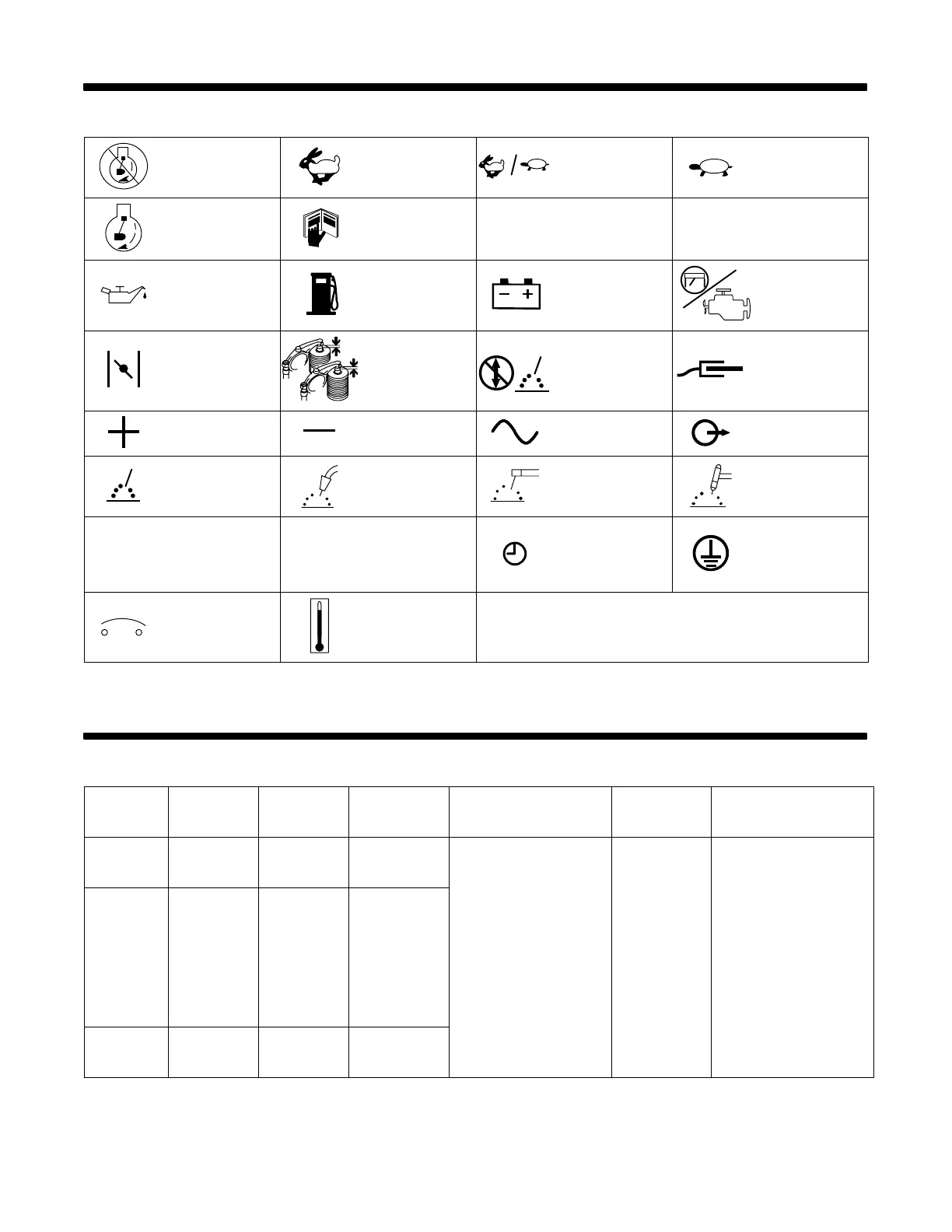
SECTION 3 − DEFINITIONS
3-1. Symbol Definitions
Stop Engine
Fast
(Run, Weld/Power)
Fast/Slow
(Run/Idle)
Slow (Idle)
Start Engine
Read Operator’s
Manual A
Amperes
V
Volts
Engine Oil Fuel Battery (Engine) Engine
Engine Choke
Check Valve
Clearance
Do not switch while
welding
Work Connection
Positive Negative
Alternating Current
(AC)
Output
Welding Arc
(Electrode)
MIG (GMAW),
Wire
Stick (SMAW) TIG (GTAW)
h
Hours
s
Seconds Time
Protective Earth
(Ground)
Circuit Protector Temperature
SECTION 4 − SPECIFICATIONS
4-1. Weld, Power, and Engine Specifications
Welding
Mode
Weld Output
Range
Rated
Welding
Output
Maximum
Open Circuit
Voltage
Generator Power Rating
Fuel
Capacity
Engine
CC/AC 50 − 225 A
225 A, 25 V,
100% Duty
Cycle
80
CC/DC 50 − 210 A
210 A, 25 V,
100% Duty
Cycle
80
Single−Phase
10kVA/kW
84/42A 120/240V AC
60 Hz
Three−Phase
11 kVA/kW
13A, 480 V AC
60 Hz
(while not welding)
12 gal
(45 L) Tank
Kohler CH-23
Air-Cooled, Two-Cylinder,
Four-Cycle, 23 HP
Gasoline Engine
CV/DC 19 − 28 V
200 A, 20 V,
100% Duty
Cycle
33