A complete Parts List is available at www.MillerWelds.com
OM-4436 Page 10
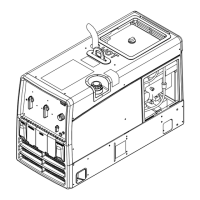
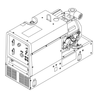
4-2. Dimensions, Weights, and Operating Angles
Dimensions
A
Height
33-1/2 in (851 mm)
(To Top Of Exhaust)
B
C
Width 20 in (508 mm)
Do not exceed tilt angles or engine could
Depth 45-3/8 in (1153 mm)
D
be damaged or unit could tip.
Do not move or operate unit where it could
A 20 in (508 mm)
4 Holes
G
v
u
w
u
tip.
B 16-1/2 in (419 mm)
C 1-3/4 in (44 mm)
E
F
D 6-1/16 in (154 mm)
25°
E 32-3/4 in (832 mm)
F 45-3/8 in (1153 mm)
25°
25°
G 13/32 in (10 mm) Dia.
25°
Weight
Kohler-Powered Unit: 562 lb (254 kg)
800 426
En
ine End
Lifting Eye Weight Rating:
1280 lb (580 kg)
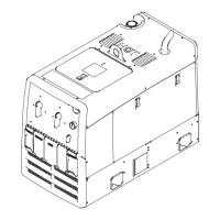
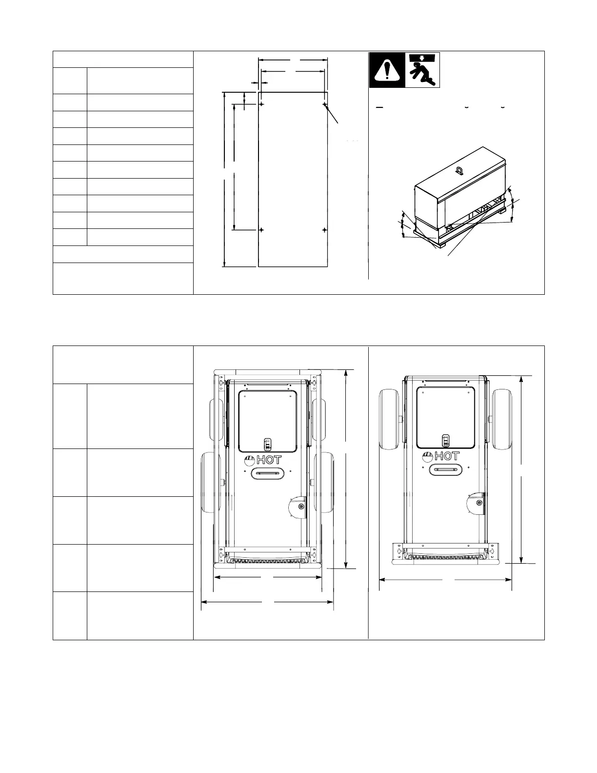
4-3. Dimensions For Units With Optional Running Gear
Dimensions
Height
All Running Gear Options:
42-1/2 in (1079 mm)
(To Top Of Handle
Assembly)
A
Protective Cage Width:
26 in (660 mm)
D
B
Running Gear Width:
32 in (813 mm)
C
Protective Cage Length:
48 in (1219 mm)
B
A
D
Running Gear Length:
45−1/2 in (1156 mm)
B