OM-4436 Page 52
SECTION 14 − MIG WELDING (GMAW) GUIDELINES
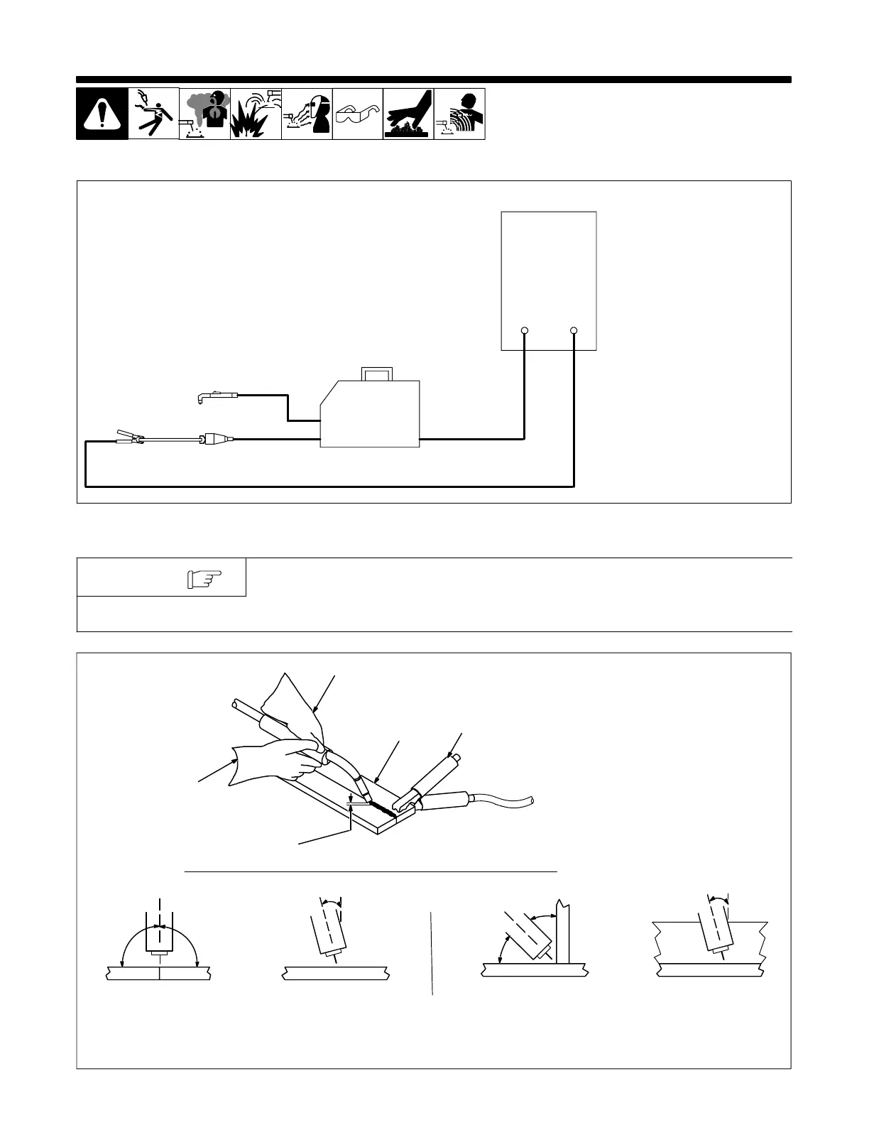
14-1. Typical MIG Process Connections Using A Voltage-Sensing Wire Feeder
Weld current can damage
electronic parts in vehicles.
Disconnect both battery
cables before welding on a
vehicle. Place work clamp as
close to the weld as possible.
Voltage sensing wire feeders are
used with constant current (CC) or
constant voltage (CV) power
sources (14 pin receptacle not re-
quired).
If using a CC or CV welding power
source without a weld output con-
tactor, use optional secondary con-
tactor.
For GMAW, use optional gas valve.
Voltage
Sensing Wire
Feeder
Constant
Current (CC)
Or Constant
Voltage (CV)
Power Source
Work Lead
Electrode Lead
Workpiece
Work Clamp Voltage
Sensing Clamp
Gun
802 488
14-2. Holding And Positioning Welding Gun
Welding wire is energized when gun trigger is pressed. Before lowering helmet and
pressing trigger, be sure wire is no more than 1/2 in (13 mm) past end of nozzle,
and tip of wire is positioned correctly on seam.
NOTE
1 Hold Gun and Control Gun
Trigger
2 Workpiece
3 Work Clamp
4 Electrode Extension (Stickout)
1/4 to 1/2 in (6 To 13 mm)
5 Cradle Gun and Rest Hand on
Workpiece
2
3
5
4
90° 90°
0°-15°
45°
45°
GROOVE WELDS
FILLET WELDS
End View Of Work Angle Side View Of Gun Angle
End View Of Work Angle Side View Of Gun Angle
1
0°-15°
S-0421-A