EasyManua.ls Logo

Miller Bobcat 250 User Manual

Miller Bobcat 250
80 pages
To Next Page IconTo Next Page
Page #1 background imageLoading...
Page #1 background image
OWNER’S MANUAL
OM-249336M
2019-05
Processes
Stick (SMAW) Welding
MIG (GMAW) Welding
Flux Cored (FCAW) Welding
TIG (GTAW) Welding
Description
Engine Driven Welder/Generator
For product information,
Owner’s Manual translations,
and more, visit
www.MillerWelds.com
Bobcat
250

Table of Contents

Other manuals for Miller Bobcat 250

Question and Answer IconNeed help?

Do you have a question about the Miller Bobcat 250 and is the answer not in the manual?

Miller Bobcat 250 Specifications

General IconGeneral
Rated Output250 A at 25 VDC, 100% Duty Cycle
Generator Power11, 000 Watts Peak, 9, 500 Watts Continuous
EngineKohler CH730
Fuel TypeGasoline
CC/CVCC/CV
PhaseSingle-phase
Frequency60 Hz
TypeEngine Driven Welder
Welding ProcessesStick (SMAW), MIG (GMAW), Flux-Cored (FCAW), TIG (GTAW)
Fuel Tank Capacity12 gallons
Welding Amperage Range40 - 250 A
Open Circuit Voltage80 VDC
Voltage120/240 V
Outlet Types120V 20A Duplex, 240V 50A

Summary

SECTION 1 – SAFETY PRECAUTIONS - READ BEFORE USING

1-1. Symbol Usage

Explains safety symbols used throughout the manual.

1-2. Arc Welding Hazards

Details potential dangers associated with arc welding processes.

1-3. Engine Hazards

1-4. Compressed Air Hazards

1-5. Additional Symbols For Installation, Operation, And Maintenance

1-6. California Proposition 65 Warnings

1-7. Principal Safety Standards

1-8. EMF Information

SECTION 3 – DEFINITIONS

3-1. Additional Safety Symbol Definitions

Defines safety symbols specific to CE products.

3-2. Miscellaneous Symbol Definitions

Defines general symbols used throughout the manual.

SECTION 4 – SPECIFICATIONS

4-1. Serial Number And Rating Label Location

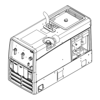
Indicates where to find serial and rating plate information.

4-2. Weld, Power, And Carbureted Engine Specifications (Kohler CH730)

Technical specifications for CH730 engine models.

4-3. Weld, Power, and EFI Engine Specifications (Kohler ECH730)

Technical specifications for ECH730 engine models.

4-4. Environmental Specifications

Details operating and storage temperature ranges.

4-5. Dimensions, Weights, And Operating Angles

4-6. Duty Cycle And Overheating

4-7. Fuel Consumption

4-8. Generator Power Curve

4-9. Volt-Ampere Curves

SECTION 5 – INSTALLATION

5-1. Installing Welder/Generator

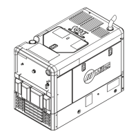
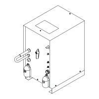
Instructions for mounting and securing the welder/generator unit.

5-2. Grounding Generator to Truck or Trailer Frame

5-3. Installing Exhaust Pipe

5-4. Engine Prestart Checks

5-5. Connecting Or Replacing The Battery

5-6. Electronic Fuel Injection (EFI) System And Battery Information

5-7. Weld Output Terminals

5-8. Connecting Weld Output Cables

5-9. Selecting Cable Sizes*

SECTION 6 – OPERATION

6-1. Front Panel Controls (See Section 6-2)

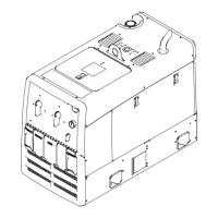
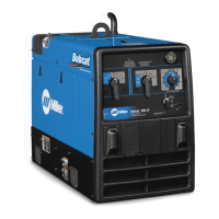
Overview of the welder's front panel controls.

6-2. Description of Controls (See Section 6-1)

6-3. Cold Weather Engine Operation

6-4. Typical Stick Welding Connections And Control Settings

6-5. Typical MIG Welding Connections and Settings

6-6. Typical MIG Connections And Settings Using Weld Control And Spoolgun

6-7. Fuel/Hour Gauge Descriptions

SECTION 7 – OPERATING AUXILIARY EQUIPMENT

7-1. Generator Power Receptacles

Details the available generator power receptacles and their ratings.

7-2. GFCI Receptacle Information, Resetting, And Testing

7-3. Simultaneous Weld And Power

7-4. Wiring Optional 120/240 Volt Plug

SECTION 8 – MAINTENANCE AND TROUBLESHOOTING

8-1. Routine Maintenance

Schedule and tasks for routine maintenance.

8-2. Maintenance Label

8-3. Servicing Air Cleaner

8-4. Electronic Fuel Injection (EFI) System And Servicing Information

8-5. Overload Protection

8-6. Changing Engine Oil, Oil Filter, And Fuel Filter

8-7. Adjusting Engine Speed (Kohler CH730 Carbureted Units)

8-8. Adjusting Engine Speed (Kohler ECH730 EFI Units)

8-9. Troubleshooting

SECTION 9 – PARTS LIST

9-1. Recommended Spare Parts

List of recommended spare parts with part numbers and descriptions.

SECTION 10 – ELECTRICAL DIAGRAMS

Figure 10-1. Circuit Diagram For Welder/Generator

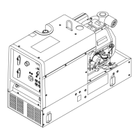
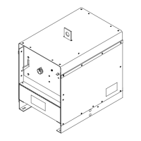
The main electrical circuit diagram for the unit.

SECTION 11 – GENERATOR POWER GUIDELINES

11-1. Selecting Equipment

Guidance on selecting auxiliary equipment for use with the generator.

11-2. Grounding Generator to Truck or Trailer Frame

Procedures for safely grounding the generator to a vehicle frame.

11-3. Grounding When Supplying Building Systems

11-4. How Much Power Does Equipment Require?

11-5. Approximate Power Requirements For Industrial Motors

11-6. Approximate Power Requirements For Farm/Home Equipment

11-7. Approximate Power Requirements For Contractor Equipment

11-8. Power Required To Start Motor

11-9. How Much Power Can Generator Supply?

11-10. Typical Connections To Standby Power

11-11. Selecting Extension Cord (Use Shortest Cord Possible)

SECTION 12 – STICK WELDING (SMAW) GUIDELINES

12-1. Stick Welding Procedure

Step-by-step guide for performing stick welding.

12-2. Electrode And Amperage Selection Chart

12-3. Striking An Arc

12-4. Positioning Electrode Holder

12-5. Poor Weld Bead Characteristics

12-6. Good Weld Bead Characteristics

12-7. Conditions That Affect Weld Bead Shape

12-8. Electrode Movement During Welding

12-9. Welding Lap Joints

12-10. Welding Groove (Butt) Joints

12-11. Welding T-Joints

12-12. Weld Test

12-13. Troubleshooting

SECTION 13 – GMAW WELDING (MIG) GUIDELINES WHEN USING A VOLTAGE-SENSING FEEDER

13-1. Typical GMAW (MIG) Process Connections Using A Voltage-Sensing Wire Feeder

Connections for MIG welding with a voltage-sensing wire feeder.

13-2. Holding And Positioning Welding Gun

13-3. Conditions That Affect Weld Bead Shape

13-4. Gun Movement During Welding

13-5. Poor Weld Bead Characteristics

13-6. Good Weld Bead Characteristics

13-7. Troubleshooting – Excessive Spatter

13-8. Troubleshooting – Porosity

13-9. Troubleshooting – Excessive Penetration

13-10. Troubleshooting – Lack Of Penetration

13-11. Troubleshooting – Incomplete Fusion

13-12. Troubleshooting – Burn-Through

13-13. Troubleshooting – Waviness Of Bead

13-14. Troubleshooting – Distortion

13-15. Common MIG Shielding Gases

13-16. Troubleshooting Guide For Semiautomatic Welding Equipment

TRUE BLUE WARRANTY

LIMITED WARRANTY

Details the terms and conditions of the limited warranty.

Owner's Record

For Service

Related product manuals