DANGER! − Indicates a hazardous situation which, if not
avoided, could result in death or serious injury. The possible
hazards are shown in the adjoining symbols or explained in
the text.
Have only trained and qualied persons install, operate, or
service this unit. Read the safety information at the beginning
of these instructions and in each section. Call your distributor
if you do not understand the directions. For WELDING SAFETY
and EMF information, read owner’s manual(s).
Falling equipment can injure, and damage equipment. Never
put any body part under unit while lifting. Lifting forks must
extend out opposite side of base. Lift and support unit only
with proper equipment and correct procedures. Follow the
guidelines in the Applications Manual for the Revised NIOSH
Lifting Equation (Publication No. 94−110) when manually
lifting heavy parts or equipment.
Wear safety glasses with side shields.
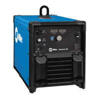
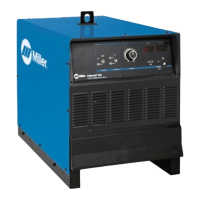
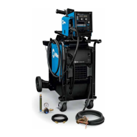
Deltaweld
®
350 Quick Setup Guide
2 x 3/4 in.
1/2 in., 9/16 in., 3/4 in.
1. Getting Started
Ensure sufcient room exists behind assembly before
removing it from pallet.
Remove shrink wrap. Remove and unbox all packages from
the cart. Verify that all parts are present.
Wire feeder
Accessories kit includes weld cables, gas regulator,
gas hose, control cable, drive roll kit, and hardware kit.
Hardware kit includes gas bottle chain, 1/2 in. bolt,
and washer.
Bernard
™
MIG gun
1
2
3
1
2
3
2. Removing Integrated Cart From Pallet
Have only trained and qualied persons
install power cable and select input voltage.
See welding power source Owner’s Manual.
Do not connect power until assembly is complete.
See welding power source Owner’s Manual.
Remove the two lag bolts and two mounting brackets
from the rear of the cart. Remove the bolt from the
front underside of the cart.
Push cart backwards off the front and rear blocks.
When wheels and casters are on the pallet, slide rear
block out of the way. Continue to push cart backward
until wheels and casters are on the ground.
1/2 in.
1
2
1
1
2
2
Safety Symbol Denitions
Tools Needed
Scan this code or visit
MillerWelds.com/deltaweldsetup
to view a video of the Deltaweld 350
integrated cart setup.
1