
Y
yvonneburchAug 7, 2025
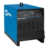
How to fix a Miller DELTAWELD 652 when fuse F1 opens?
- WwallaceryanAug 7, 2025
How to fix a Miller Welding System when fuse F1 opens? Replace F1. Also, always disconnect input power before opening the rear access door.
How to fix a Miller DELTAWELD 652 when fuse F1 opens?
How to fix a Miller Welding System when fuse F1 opens? Replace F1. Also, always disconnect input power before opening the rear access door.
What to do if my Miller DELTAWELD 652 Welding System experiences a short circuit shutdown?
What to do if my Miller Welding System experiences a short circuit shutdown? This can occur if the contact tip is shorted and sticks to the workpiece. To resolve this, release the gun trigger, turn off the unit, and remove the contact tip from the workpiece. Inspect the contact tip and replace it if it's damaged. Then, turn the unit back on to resume operation.
What to do if Miller Welding System has a short circuit shutdown?
If the Miller Welding System experiences a short circuit shutdown because the contact tip is shorted and sticks to the workpiece, release the gun trigger, turn the unit off, and remove the contact tip from the workpiece. Inspect the contact tip, and replace it if it is damaged. After these steps, turn the unit back on to continue operation.
| Brand | Miller |
|---|---|
| Model | DELTAWELD 652 |
| Category | Welding System |
| Language | English |