EasyManua.ls Logo

Miller DIVERSION 165 User Manual

Miller DIVERSION 165
40 pages
To Next Page IconTo Next Page
Page #1 background imageLoading...
Page #1 background image
Processes
OM-263920B 2018-05
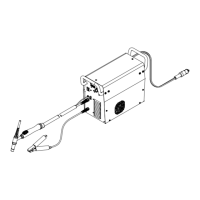
DIVERSIONt180 w/Auto-Linet
Processes
TIG (GTAW) Welding
Description
Diversion 180: 115-230 VAC Arc Weld-
ing Power Source w/Auto-Linet
File: TIG (GTAW)
Diversion 165: 230 Volt Arc Welding
Power Source
DIVERSIONt165 And
Scan this tag with your mobile device
to learn more about this product.
Individual carrier rates may apply.
Start by downloading the free mobile
app at http://gettag.mobi
(WP17 Torch)
For product information,
Owner’s Manual translations,
and more, visit
www.MillerWelds.com
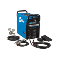
Table of Contents

Questions and Answers:

Miller DIVERSION 165 Specifications

General IconGeneral
Input Frequency50/60 Hz
Amperage Range10 - 165 A
Weldable MaterialsSteel, Stainless Steel, Aluminum
Weight50 lb (22.7 kg)
ProcessesTIG (GTAW), Stick (SMAW)
TIG Lift ArcYes
Input Voltage120 V / 240 V
Input Phase1-Phase
Stick Electrode SizeUp to 3/32 in
TIG Electrode SizeUp to 3/32 in

Summary

From Miller to You

Safety Precautions

1-1. Symbol Usage

Explanation of warning symbols used throughout the manual to indicate potential hazards.

1-2. Arc Welding Hazards

Details on dangers associated with arc welding, including electric shock and proper grounding.

Fumes, Gases, and Environmental Hazards

Covers risks from fumes, gases, arc rays, fire, explosions, EMF, and noise.

Cylinder and Equipment Hazards

Addresses risks from gas cylinders, falling equipment, moving parts, sparks, and electrical hazards.

1-3. Additional Symbols for Installation, Operation, and Maintenance

Details additional symbols related to installation, operation, and maintenance procedures.

Interference and Standards

Information on HF and arc welding interference, Prop 65, safety standards, and EMF.

Definitions

3-1. Additional Safety Symbols And Definitions

Details and meanings of additional safety symbols and related definitions for hazard identification.

3-2. Miscellaneous Symbols And Definitions

Glossary of common symbols and their meanings for operational context and understanding.

Specifications

4-1. Serial Number And Rating Label Location

Guidance on finding the unit's serial number and rating information for identification.

4-2. Specifications

Detailed electrical and performance specifications for Diversion 180 and Diversion 165 models.

4-3. Included with Your Unit

List of items that come standard with the welding power source package.

4-4. Dimensions And Weights

Physical size and weight specifications for the welding unit, aiding in placement and handling.

4-5. Environmental Specifications

Details on IP rating and operating/storage temperature ranges for optimal equipment performance.

4-6. Duty Cycle Charts

Graphical representation of output amperage versus duty cycle for different models to prevent overheating.

Installation

5-1. Selecting A Location (All Models)

Guidance on choosing a suitable and safe location for the welding unit, considering airflow and movement.

5-2. Remote Receptacle For Optional Foot Control

Information on using the dedicated receptacle for connecting an optional foot control pedal.

5-3. Shielding Gas Connections

Procedures and tools required for connecting the shielding gas supply to the unit.

5-4. Electrical Service Guide (Diversion 165)

Electrical requirements and recommendations for connecting the Diversion 165 model to power.

5-5. Electrical Service Guide (Diversion 180)

Electrical requirements and recommendations for connecting the Diversion 180 model to power.

5-6. Selecting Extension Cord (Use Shortest Cord Possible)

Guidelines for choosing the correct extension cord based on voltage and length to minimize voltage drop.

5-7. Connecting 230 Volts Input Power For Diversion 165 Models

Step-by-step instructions for connecting the Diversion 165 to a 230V input power source.

5-8. Connecting 115 Volts Input Power For Diversion 180 Models

Instructions for connecting the Diversion 180 to a 115V input power source, detailing the Auto-Line feature.

5-9. Connecting 230 Volts Input Power For Diversion 180 Models

Instructions for connecting the Diversion 180 to a 230V input power source, detailing the Auto-Line feature.

5-10. Multi-Voltage Plug (MVP) Connection

Guide to selecting and connecting the appropriate MVP plug for various power supply receptacles.

Operation

6-1. Controls For Diversion 165 Models

Detailed explanation of the controls and indicators on the Diversion 165 model.

6-2. Controls For Diversion 180 Models

Detailed explanation of the controls and indicators on the Diversion 180 model.

Maintenance and Troubleshooting

7-1. Routine Maintenance

Recommended maintenance tasks and their frequencies to ensure optimal performance and longevity.

7-2. Circuit Breaker CB1

Information regarding the unit's circuit breaker and its function in protecting the equipment.

7-3. Meter Troubleshooting Displays For Diversion 180 Models

Interpretation of error codes and displays shown on the unit's meter for fault diagnosis.

7-4. Troubleshooting

A table listing common problems and their suggested remedies for user-level troubleshooting.

Electrical Diagrams

Figure 8-1. Circuit Diagram For Diversion 165 Models

Detailed electrical schematic illustrating the internal components and wiring of the Diversion 165.

Figure 8-2. Circuit Diagram For Diversion 180 Models

Detailed electrical schematic illustrating the internal components and wiring of the Diversion 180.

High Frequency (HF) Interference

9-1. Welding Processes Requiring High Frequency

Explanation of which welding processes utilize high frequency for arc starting and stabilization.

9-2. Installation Showing Possible Sources Of HF Interference

Identification of common sources that can cause or contribute to high frequency interference in the work area.

9-3. Recommended Installation To Reduce HF Interference

Guidelines for proper installation and grounding to minimize high frequency interference.

Tungsten Electrode Selection and Preparation

10-1. Selecting Tungsten Electrode (Wear Clean Gloves To Prevent Contamination Of Tungsten)

Recommendations for selecting tungsten electrode diameter, type, and amperage range for different materials.

B. Electrode Composition

Overview of different tungsten types, their properties, and recommended applications for welding.

10-2. Preparing Tungsten Electrode For DC Electrode Negative (DCEN) Welding Or AC Welding With Inverter Machines

Instructions on proper grinding techniques for tungsten electrodes to ensure stable arc performance.

TIG Welding Guidelines (GTAW)

11-1. Positioning The Torch

Guidance on correct torch angle, tungsten extension, and arc length for effective TIG welding.

11-2. Torch Movement During Welding

Techniques for moving the torch and filler rod during TIG welding for consistent weld beads.

11-3. Positioning Torch Tungsten For Various Weld Joints

Recommended torch and tungsten angles for various types of weld joints like butt, lap, and corner.

Warranty Information

Owner's Record and Service Information

Related product manuals