Do you have a question about the Miller Deltaweld 500 and is the answer not in the manual?
Explains the meaning of safety symbols used in the manual.
Details hazards associated with arc welding processes and safe practices.
Discusses hazards related to installation, operation, and maintenance.
Provides warnings regarding chemical exposure from the product.
Lists key safety standards and their sources relevant to welding.
Explains electromagnetic fields (EMF) and interference with medical devices.
Explains the meaning of safety symbols used in the manual in French.
Details hazards associated with arc welding processes and safe practices in French.
Warnings regarding chemical exposure as per California Proposition 65.
Lists key safety standards and their sources relevant to welding.
Explains electromagnetic fields (EMF) and interference with medical devices.
Defines safety symbols that may appear only on CE products.
Provides definitions for various symbols used throughout the manual.
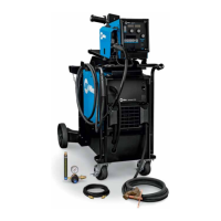
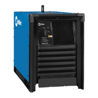
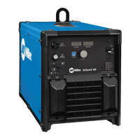
Highlights key features and advantages of the welding power source.
Indicates where to find the serial number and rating information on the unit.
Provides information on the End User License Agreement for software.
Advises on the use and modification of default welding parameters and settings.
Presents detailed technical specifications of the unit, including input/output ratings.
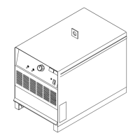
Provides the physical dimensions and weight of the welding power source.
Details IP rating and temperature ranges for operation and storage.
Explains duty cycle percentages and overheating prevention measures.
Describes the output characteristics of the power source for different welding processes.
Guides on choosing a suitable location for the welding unit, considering movement and airflow.
Details procedures for safely checking and discharging input capacitor voltage.
Explains how to select the correct input voltage setting for the unit.
Provides guidelines for selecting appropriate weld cable sizes based on amperage and length.
Identifies the positive and negative weld output terminals on the unit.
Provides instructions for properly connecting weld output cables to the terminals.
Offers tips on arranging welding cables to minimize circuit inductance and improve performance.
Details the pinouts and functions of the Remote 14 receptacle.
Identifies supplementary protectors (circuit breakers) for various receptacles.
Provides recommendations for electrical service requirements, including voltage, current, and cable sizes.
Illustrates the correct procedure for connecting input power to the welding unit.
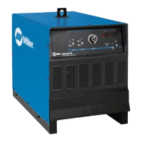
Describes the components and indicators on the front panel of the welding unit.
Shows a typical connection diagram for MIG, Flux Cored welding processes.
Illustrates the typical connection for the Carbon Arc Cutting process.
Outlines routine maintenance tasks and their recommended frequency.
Provides instructions on how to clean the inside of the unit by blowing out dust.
Explains how to diagnose faults using blink codes indicated on the front panel.
Describes fault messages displayed on units with an optional display.
Provides a table to help diagnose faults based on blink codes and display messages.
Offers solutions for common operational problems and troubleshooting steps.
Presents the detailed circuit diagram for the Deltaweld 500 model.
Outlines the terms and conditions of the limited warranty for Miller equipment.
Section for recording personal details about the purchased equipment.
Provides contact information for obtaining service and support for the equipment.
| Brand | Miller |
|---|---|
| Model | Deltaweld 500 |
| Category | Welding System |
| Language | English |