
V
Veronica GarciaAug 3, 2025
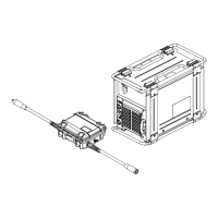
What to do if cables and cords are cracked on Miller FieldPro Smart Feeder CE Welding System?
- CCorey HayesAug 3, 2025
Cracked cables and cords on your Miller Welding System should be repaired or replaced to ensure safe and efficient operation.