
T
Timothy OsborneAug 6, 2025
What to do if the drive motor becomes inoperative in Miller Millermatic 140 Auto-Set?
- WWayne FlemingAug 7, 2025
If the drive motor becomes inoperative, cycle the unit power off and back on again.
What to do if the drive motor becomes inoperative in Miller Millermatic 140 Auto-Set?
If the drive motor becomes inoperative, cycle the unit power off and back on again.
What to do if the contact tip has stuck to the workpiece with Miller Welding System?
If the contact tip has stuck to the workpiece, release the gun trigger, turn off the unit, and remove the contact tip from the workpiece.
What to do if contact tip is shorted to workpiece and Miller Millermatic 140 Auto-Set shuts down welding output?
If the contact tip is shorted to the workpiece and the unit shuts down welding output, release the gun trigger to reset the unit.
Explains safety symbols used in the manual to identify potential hazards and necessary precautions.
Details hazards associated with arc welding, including electric shock, fumes, sparks, noise, and cylinder safety.
Illustrates symbols for specific hazards like fire, falling equipment, overheating, sparks, static discharge, and moving parts.
Provides warnings regarding chemicals in welding fumes, gases, and battery components known to cause cancer or birth defects.
Lists key safety standards and organizations relevant to welding, cutting, and allied processes for compliance.
Discusses electromagnetic fields (EMF) generated by welding and their potential interference with medical implants.
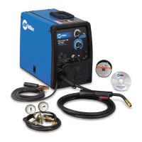
Details the technical specifications for 115 VAC and 230 VAC models, including output, amperage, voltage, and dimensions.
Explains duty cycle percentages and the consequences of overheating, including operational limits and cooling procedures.
Presents volt-ampere curves that illustrate the minimum and maximum voltage and amperage output capabilities of the welding source.
Provides step-by-step instructions for correctly installing the welding gun onto the unit.
Details the procedure for installing the work clamp, emphasizing the importance of proper connection hardware.
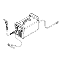
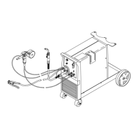
Illustrates the correct routing of the work cable inside the welding unit for safe and efficient operation.
A table outlining recommended polarity (DCEP/DCEN) for different welding processes like GMAW and FCAW.
Guides users on how to change the welding polarity for solid wire (DCEP) and flux core wire (DCEN) processes.
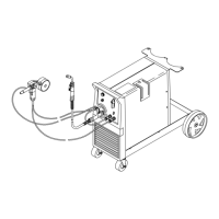
Instructions on connecting the gas cylinder, regulator/flowmeter, and hose for shielding gas setup.
Identifies the location of the serial and rating labels on the unit for reference and warranty purposes.
Advises on choosing a suitable location and connecting the input power for the 115 VAC model.
Guides users on selecting a location and connecting input power for the 230 VAC model, including safety precautions.
Provides recommendations for electrical service, including voltage, amperage, fuse rating, and conductor size for the 230 VAC model.
Details the process for installing wire spools and adjusting hub tension for proper wire feeding.
Step-by-step instructions for threading welding wire through the drive mechanism and into the gun.
Outlines the procedure for safely removing the MIG gun from the welding power source.
Guides on installing a switch for an optional spool gun, including wiring and operational placement.
Instructions on connecting the spool gun to the Millermatic 140/180 unit, ensuring proper seating and polarity.
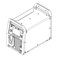
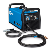
Explains the controls for the 115 VAC Auto-Set model, including wire speed, voltage, and Auto-Set functionality.
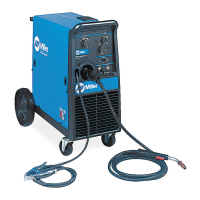
Details the controls for the 230 VAC Auto-Set model, covering wire speed, voltage, and Auto-Set operation.
Provides a chart of recommended settings for welding mild steel with the 115 VAC Auto-Set model.
Instructions on how to use the manual setup to select voltage and wire speed based on metal thickness and wire size.
Offers recommended settings for welding mild steel with the 230 VAC Auto-Set model.
Outlines a schedule for routine maintenance tasks, including checking, cleaning, and replacing parts.
Explains the overload protection mechanism (CB1) and how to reset it if the unit shuts down.
Describes the drive motor protection and tip saver features that prevent damage during operation.
Details the procedure for changing the drive roll and wire inlet guide to accommodate different wire sizes.
A table listing common welding problems, their probable causes, and recommended remedies for quick resolution.
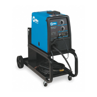
Illustrates the standard setup for MIG welding, showing connections between shielding gas, wire feeder, and workpiece.
Provides guidelines for setting wire speed, voltage, and amperage based on material thickness and wire size.
Explains proper techniques for holding and positioning the welding gun for groove and fillet welds.
Discusses factors influencing weld bead shape, including gun angle, travel speed, and electrode extension.
Describes recommended gun movements for achieving satisfactory weld joints, such as stringer and weave beads.
Illustrates common characteristics of poor weld beads, such as spatter, porosity, and poor penetration.
Shows examples of good weld bead characteristics, including uniform bead, proper penetration, and minimal spatter.
Identifies causes and corrective actions for excessive spatter during MIG welding operations.
Details potential causes and solutions for porosity (small holes) in MIG weld metal.
Addresses issues of excessive penetration, where weld metal melts through the base metal.
Explains how to resolve lack of penetration, characterized by shallow fusion between weld metal and base metal.
Discusses incomplete fusion, where weld metal fails to fuse properly with the base metal.
Covers troubleshooting burn-through, where weld metal melts completely through the base metal.
Addresses waviness of the weld bead, which is not parallel and does not cover the joint correctly.
Explains distortion caused by weld metal contraction and provides methods to manage it.
A chart listing common MIG shielding gases and their applications in different welding scenarios.
A guide to troubleshooting common issues with semiautomatic welding equipment, such as wire feed and gas flow problems.
Lists recommended spare parts for the welding equipment, including contact tips, liners, and nozzles.
Details optional drive rolls available for different wire diameters and feed head assemblies.
Lists available options for the equipment, such as the M-100 replacement gun.
| Brand | Miller |
|---|---|
| Model | Millermatic 140 Auto-Set |
| Category | Welding System |
| Language | English |