. A complete Parts List is available at www.MillerWelds.com
OM-283935 Page 22
5-6. Selecting Cable Sizes*
NOTICE − The Total Cable Length in Weld Circuit (see table below) is the combined length of both weld cables. For example, if the power source
is 100 ft (30 m) from the workpiece, the total cable length in the weld circuit is 200 ft (2 cables x 100 ft). Use the 200 ft (60 m) column to determine
cable size.
Weld Cable Size** and Total Cable (Copper) Length in Weld Circuit
Not Exceeding***
100 ft (30 m) or Less
150 ft
(45 m)
200 ft
(60 m)
250 ft
(70 m)
300 ft
(90 m)
350 ft
(105 m)
400 ft
(120 m)
Welding
Amperes
10 − 60%
Duty
Cycle
AWG (mm
2
)
60 − 100%
Duty Cycle
AWG (mm
2
)
10 − 100% Duty Cycle
AWG (mm
2
)
100 4 (20) 4 (20) 4 (20) 3 (30) 2 (35) 1 (50) 1/0 (60) 1/0 (60)
150 3 (30) 3 (30) 2 (35) 1 (50) 1/0 (60) 2/0 (70) 3/0 (95) 3/0 (95)
200 3 (30) 2 (35) 1 (50) 1/0 (60) 2/0 (70) 3/0 (95) 4/0 (120) 4/0 (120)
250 2 (35) 1 (50) 1/0 (60) 2/0 (70) 3/0 (95) 4/0 (120) 2x2/0 (2x70) 2x2/0 (2x70)
300 1 (50) 1/0 (60) 2/0 (70) 3/0 (95) 4/0 (120) 2x2/0 (2x70) 2x3/0 (2x95) 2x3/0 (2x95)
350 1/0 (60) 2/0 (70) 3/0 (95) 4/0 (120) 2x2/0 (2x70) 2x3/0 (2x95) 2x3/0 (2x95) 2x4/0 (2x120)
400 1/0 (60) 2/0 (70) 3/0 (95) 4/0 (120) 2x2/0 (2x70) 2x3/0 (2x95) 2x4/0 (2x120) 2x4/0 (2x120)
* This chart is a general guideline and may not suit all applications. If cable overheats, use next size larger cable.
**Weld cable size (AWG) is based on either a 4 volts or less drop or a current density of at least 300 circular mils per ampere.
( ) = mm
2
for metric use.
***For distances longer than those shown in this guide, see AWS Fact Sheet No. 39, Welding Cables, available from the American Welding
Society at http://www.aws.org.
Ref. S-0007-M 2017−08
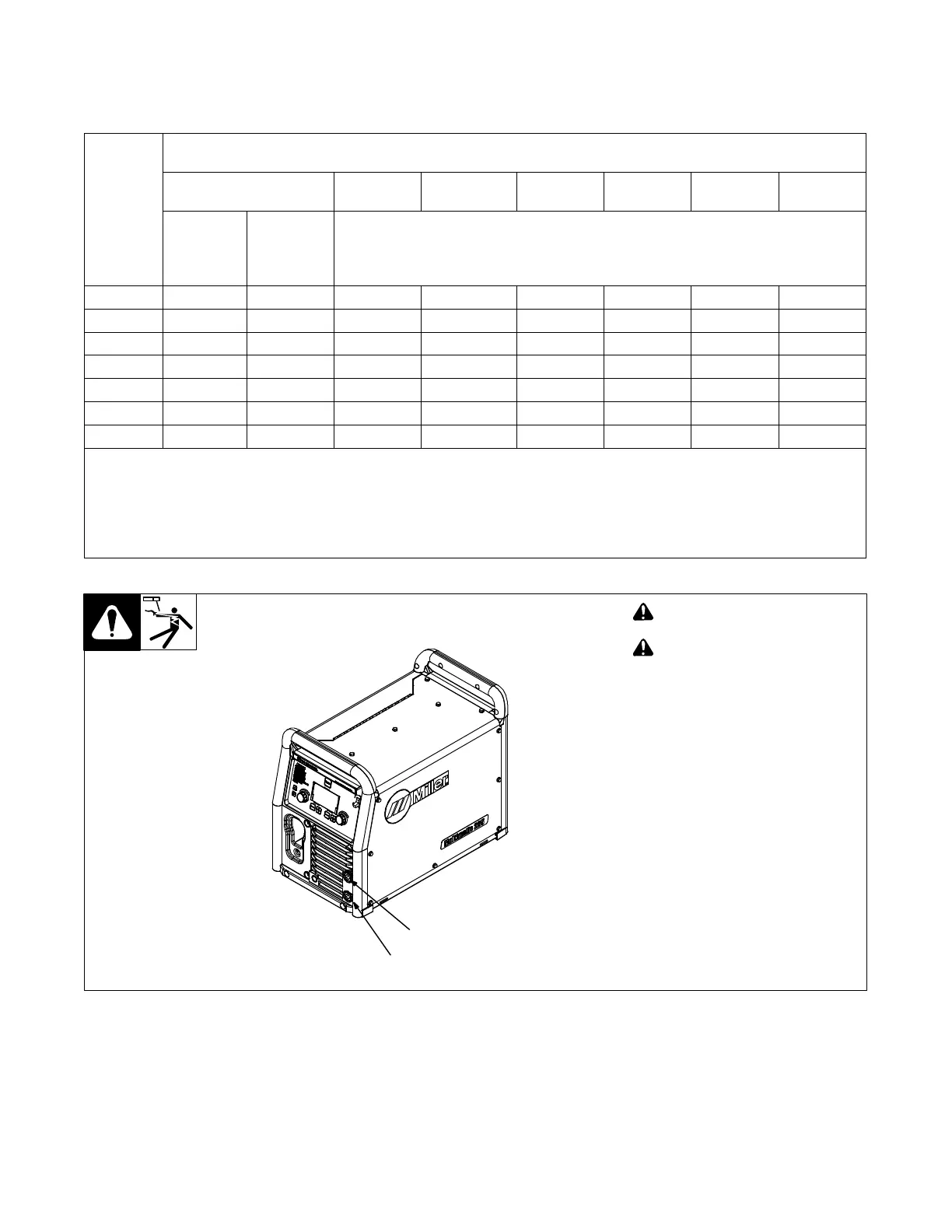
5-7. Weld Output Terminals
! Turn off power before connecting
to weld output terminals.
! Do not use worn, damaged, un-
dersized, or repaired cables.
1 Positive (+) Weld Output Terminal
2 Negative (−) Weld Output Terminal
. See Sections 5-8 thru 5-11 for infor-
mation on connecting to weld output
terminals and standard connection
diagrams.
output term1 2015−02
1
2