. A complete Parts List is available at www.MillerWelds.com
OM-283935 Page 23
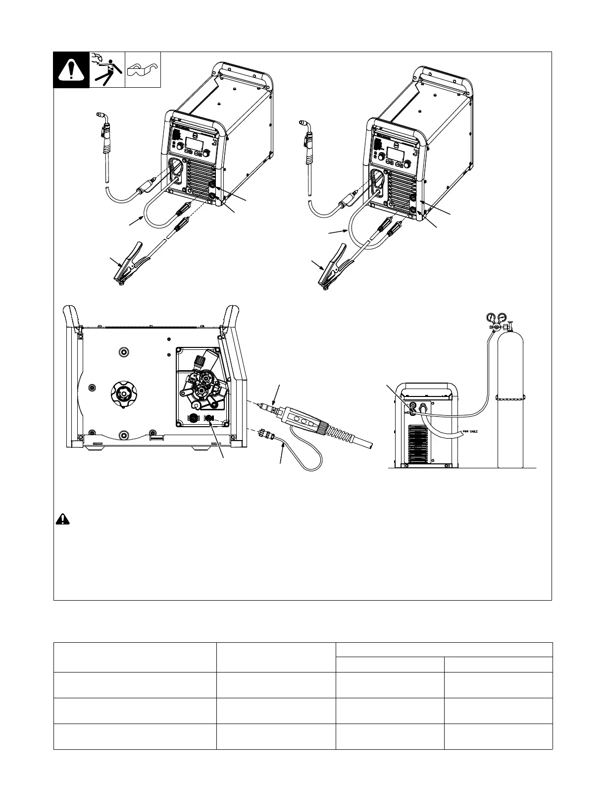
5-8. MIG Welding Connections
Ref. 280266B / Ref. 275167A / Ref. 280272C / 907728
! Turn off unit and disconnect input
power before making connections.
1 Positive Weld Output Receptacle
2 Negative Weld Output Receptacle
3 Wire Drive Assembly Cable
4 Work Clamp And Cable
Ensure all connections are tight.
5 Gun End
Connect gun end to drive assembly (see
Section 5-10).
6 Trigger Control Cable
7 Four Pin Trigger Control Cable
Receptacle
Route trigger control cable through MIG
gun hole.
Connect plug on end of cable to four pin
receptacle inside unit.
8 MIG Shielding Gas Connection
Connect supplied gas hose between regu-
lator/flowmeter
gas hose connection and
fitting on rear of welding power source.
See Section 10-16 for gas selection.
MIG/FCAW-G − DCEP
(Direct Current Electrode Positive)
FCAW-S − DCEN
(Direct Current Electrode Negative)
1
4
3
2
4
3
2
8
1
6
7
5
5-9. Process/Polarity Table
Process Polarity
Cable Connections
Wire Drive Assembly Cable Work Cable
GMAW − Solid wire with shielding gas DCEP − Reverse polarity Connect to positive (+)
output receptacle
Connect to negative (−)
output receptacle
FCAW-S − Self-shielding wire − no
shielding gas
DCEN − Straight Polarity Connect to negative (−)
output receptacle
Connect to positive (+)
output receptacle
FCAW-G − Flux-cored wire with shield-
ing gas
DCEP − Reverse Polarity Connect to positive (+)
output receptacle
Connect to negative (−)
output receptacle