. A complete Parts List is available at www.MillerWelds.com
OM-283935 Page 26
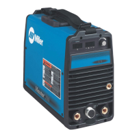
5-12. TIG Welding Connections DCEN (Direct Current Electrode Negative)
280265B / Ref. 275167A / Ref. 280272C / 907728 / Ref. 273873
! Turn off unit and disconnect input
power before making connections.
For Lift-Arc Operation
1 Positive Weld Output Receptacle
2 Negative Weld Output Receptacle
3 TIG Torch Gas Hose Fitting
4 TIG Torch And Cable
5 Work Clamp And Cable
Connect TIG torch cable to the negative
weld output receptacle. Connect work ca-
ble to positive weld output receptacle. Con-
nect TIG torch gas hose to gas hose fitting.
Ensure all connections are tight.
For remote arc starts and control, use op-
tional TIG accessory kit 301518 (contains
torch, foot pedal, 10 to 14-pin adapter, reg-
ulator, gas hose, and consumables).
Wireless foot control 300429 may also be
used with the 10 to 14-pin adapter.
6 Foot Control
7 Finger Tip Control (Optional)
8 Remote Control Cable
9 10-Pin To 14-Pin Cable Adapter (Part
No. 301545)
10 Remote Control Receptacle
Route adapter through MIG gun hole.
Connect foot control or finger tip control to
adapter. Connect adapter to remote con-
trol receptacle.
11 TIG Shielding Gas Connection
Use Argon gas for TIG welding (see
Section 5-13).
2
1
4
5
6
10
7
8
9
3
11
 Loading...
