. A complete Parts List is available at www.MillerWelds.com
OM-283935 Page 27
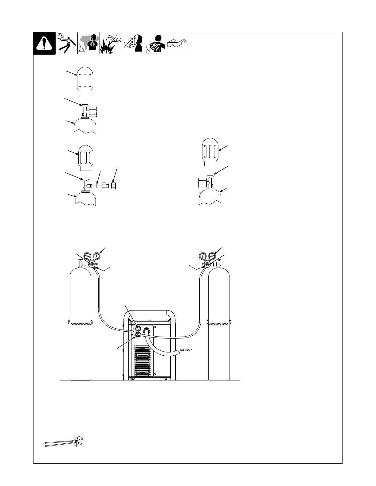
5-13. Connecting Shielding Gas Supply
Obtain gas cylinder and chain to
running gear, wall, or other
stationary support so cylinder
cannot fall and break off valve.
1 Cap
2 Cylinder Valve
Remove cap, stand to side of valve,
and open valve slightly. Gas flow
blows dust and dirt from valve.
Close valve.
3 Cylinder
4
Regulator/Flowmeter
Install so face is vertical.
5 Regulator/Flowmeter Gas
Hose Connection
6 Welding Power Source CO
2
And Mixed Gas Hose
Connection
7 Welding Power Source Argon
Gas Hose Connection
Connect gas hose between
regulator/flowmeter
gas hose
connection, and the appropriate
fitting for the gas type on rear of
welding power source.
8 Flow Adjust
Typical flow rate for shielding gas is
20 to 30 CFH (cubic feet per hour).
Check wire manufacturer’s
recommended
flow rate.
9CO
2
Adapter (Customer
Supplied)
10 O-Ring (Customer Supplied)
Install adapter with O-ring between
regulator/flowmeter
and CO
2
cylinder.
Ref. 804 654-A / 275168A / 280272C
Tools Needed:
1
2
3
Argon Gas
CO
2
Gas
1
2
3
Mixed Gas
1
2
3
10
9
8
4
5
4
5
8
6
7
MIGTIG