. A complete Parts List is available at www.MillerWelds.com
OM-283935 Page 29
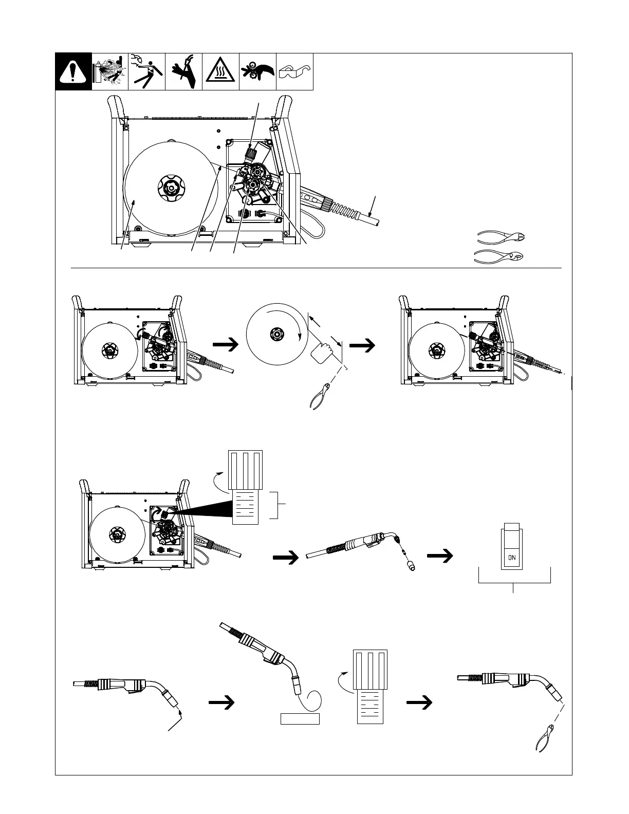
5-15. Threading Welding Wire For MIG Gun
1 Wire Spool
2 Welding Wire
3 Inlet Wire Guide
4 Pressure Adjustment Knob
5 Drive Roll
6 Outlet Wire Guide
7 Gun Conduit Cable
Lay gun cable out straight.
Tools Needed:
. Hold wire tightly to keep it
from unraveling.
WOOD
Open pressure assembly. Pull and hold wire; cut off end. Push wire through guides into gun;
continue to hold wire.
Close and tighten pressure
assembly, and let go of wire.
Remove gun nozzle and contact tip. Turn On.
Press gun trigger or jog button
until wire comes out of gun.
Reinstall contact tip and nozzle
Feed wire to check drive roll pressure.
Tighten knob enough to prevent slipping.
Cut off wire. Close
and latch door.
801083 / Ref. 800924-D / 282950-A
Tighten
1
2
3
4
Pressure
Indicator
Scale
Tighten
1
2
3
4
7
. Use pressure indicator scale to set a desired
drive roll pressure. Begin with a setting of 2.
If necessary, make additional adjustments
after trying this initial setting.
4
5
2
1
3
6
6 in.
(150 mm)