. A complete Parts List is available at www.MillerWelds.com
OM-283935 Page 31
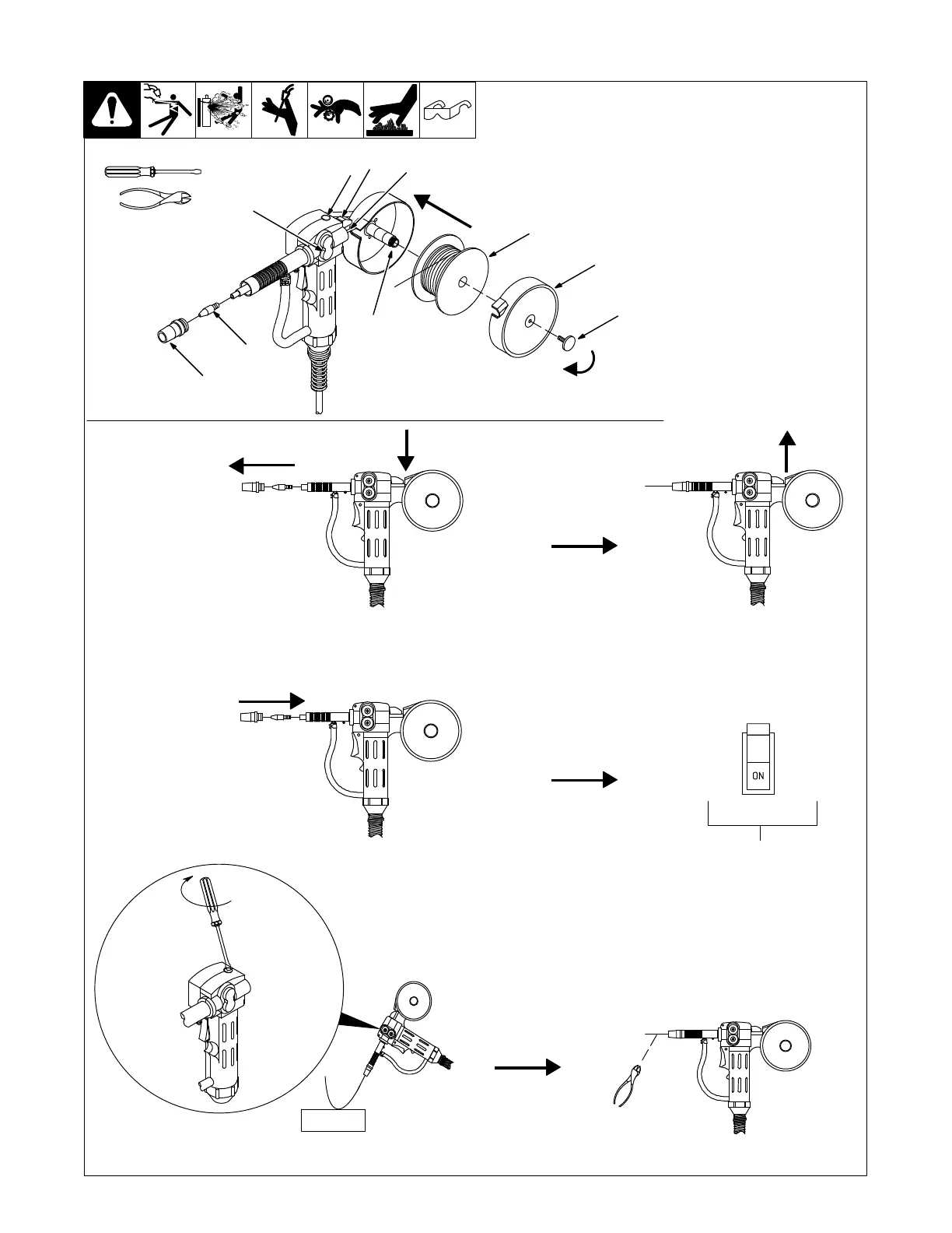
5-18. Installing Wire Spool And Threading Welding Wire For Spoolmate 100/150
804 985-A
Tools Needed:
1 Thumb Screw
2 Spool Cover
Remove thumb screw and spool
cover.
3 Spool Brake Thumbnut
4 Wire Spool
Install spool so wire feeds from top.
Turn spool brake thumbnut just so
a slight drag is felt on the wire spool.
5 Push Roll/Lower Drive Roll
6 Drive Roll Pressure
Adjustment Opening
7 Drive Roll Release Lever
(Red)
8 Wire Inlet Guide
9 Contact Tip
10 Nozzle
Remove nozzle and contact tip. Push
and hold red lever. Thread wire through
inlet guide, past push roll/drive roll, and
out end of gun 2 inches (50 mm).
Release red lever.
Turn On welding
power source power.
Install contact tip and nozzle. Reinstall
spool cover and thumb screw.
Wood
Cut off wire.
Press gun trigger to feed wire to check drive roll
pressure. Turn screw enough to prevent slipping.
. Drive roll pressure is preset for .030/.035
aluminum wire. Rotating screw clock-
wise decreases drive roll pressure
and counterclockwise increases
pressure.
4
1
5
6
7
8
10
9
3
2