. A complete Parts List is available at www.MillerWelds.com
OM-283935 Page 36
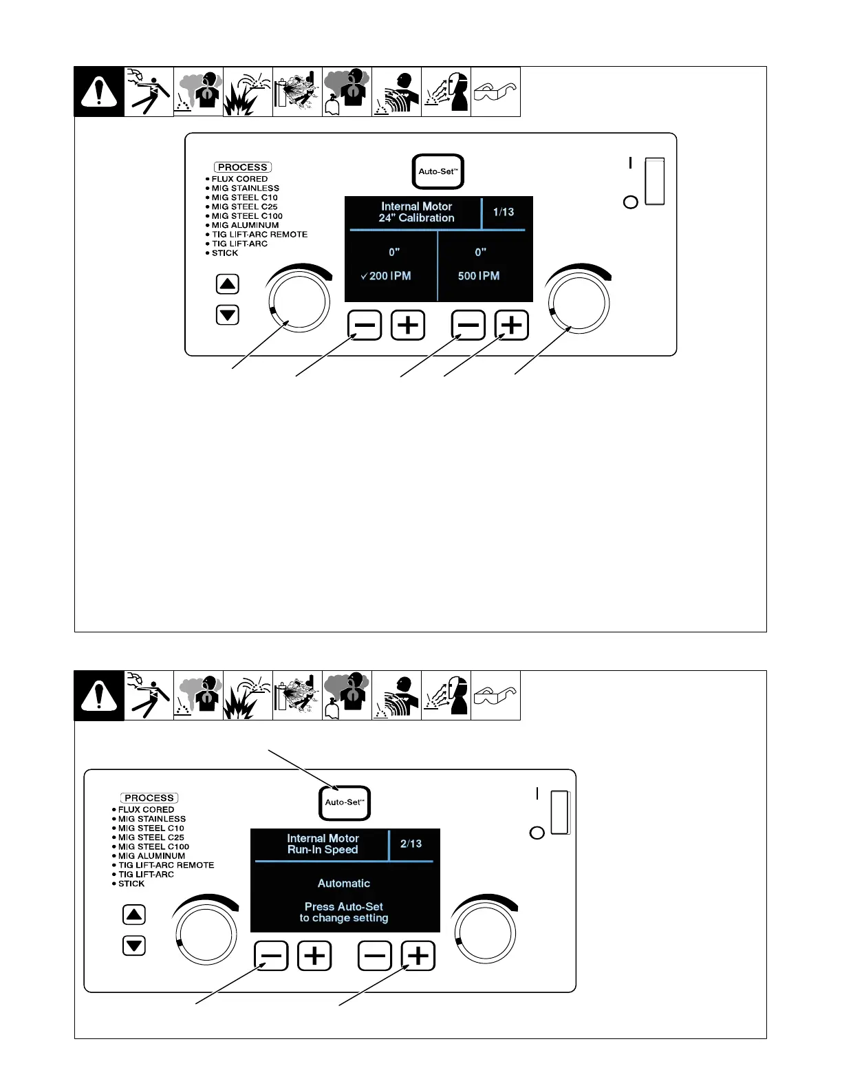
6-4. Internal Motor 24 Inch Calibration (Menu 1 Of 13)
. The unit’s internal drive motor is calibrated
at the factory. No calibration is needed un-
less drive motor or control board is
changed.
1 Lower Left Outside (−) Button
2 Lower Right Outside (+) Button
3 Lower Right Inside (−) Button
4 Left Control Encoder
5 Right Control Encoder
Cut wire flush at nozzle.
Follow instructions in Section 6-3 to enter the
setup menu.
To perform a motor calibration 24 in. run-out
test at 200 IPM, turn left Adjustment knob, and
verify that a check mark appears next to 200
IPM.
Be sure wire is cut flush at nozzle, then trigger
the MIG gun. Motor will feed approximately 24
in. of wire through gun.
Cut wire flush at nozzle and measure run-out.
If length of run-out is not 24 in., turn left Adjust-
ment knob to increase/decrease length of
run-out.
To perform a motor calibration 24 in. run-out
test at 500 IPM, turn right Adjustment knob,
and verify that a check mark appears next to
500 IPM.
Be sure wire is cut flush at nozzle, then trigger
the MIG gun. Motor will feed approximately 24
in. of wire through gun.
Cut wire flush at nozzle and measure run-out.
If length of run-out is not 24 in., turn right Ad-
justment knob to increase/decrease length of
run-out.
To exit menu, simultaneously press and re-
lease the lower left outside (−) button and low-
er right outside (+) button, or turn unit off and
on.
Ref. 281104-C
1
32
4
5
6-5. Internal Motor Run-In Speed (Menu 2 Of 13)
1 Lower Left Outside(−) Button
2 Lower Right Outside (+)
Button
3 Auto-Set Button
Follow instructions in Section 6-3 to
enter the setup menu.
To change the run−in setting, press
the Auto−Set button.
Run−in is the wire speed prior to the
welding arc being struck. When set
to Automatic, the welder deter-
mines the optimal run−in speed for
each start. When set to disabled,
the run−in speed is the same as the
weld wire speed.
To exit the menu, simultaneously
press and release the lower left out-
side (−) button and lower right out-
side (+) button, or turn unit off and
on.
Ref. 281104-C
1
2
3