. A complete Parts List is available at www.MillerWelds.com
OM-283935 Page 37
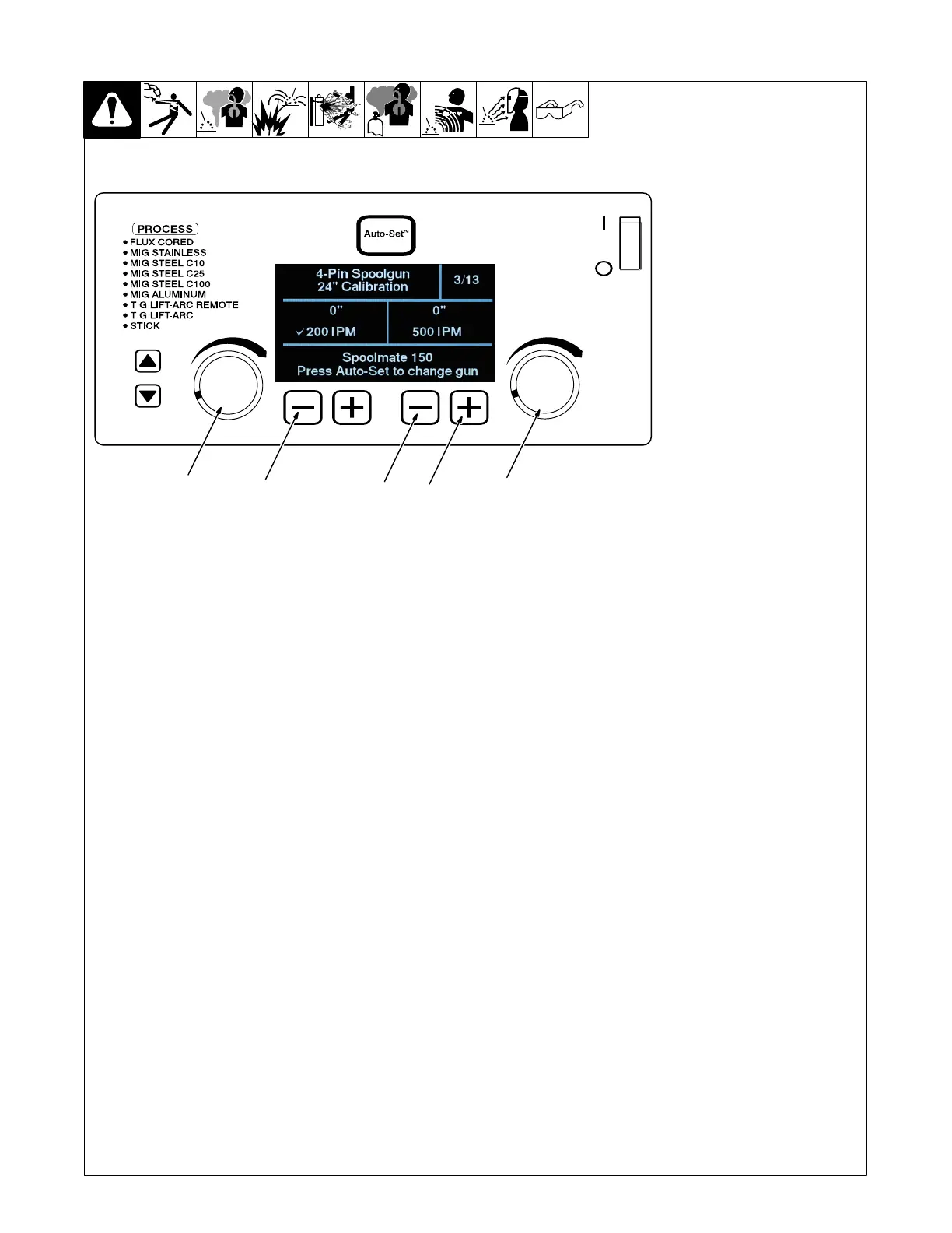
6-6. 4 Pin Spoolgun 24 Inch Calibration (Menu 3 Of 13)
1 Lower Left Outside (−) Button
2 Lower Right Outside (+)
Button
3 Lower Right Inside (−) Button
4 Left Control Encoder
5 Right Control Encoder
. Spoolmate 100 and 150 drive
motors are unique to this weld-
ing power source. Motor cali-
bration is necessary any time a
different Spoolmate 100 or 150
is connected to the Multimatic
235.Press Auto-Set button to
select Spoolmate 100 or 150.
Connect Spoolmate to unit.
Cut wire flush at nozzle.
Follow instructions in Section 6-3 to
enter the setup menu.
To perform a Spoolmate calibration
24 in. run-out test at 200 IPM, turn
left Adjustment knob, and verify that
a check mark appears next to 200
IPM.
Cut wire flush at nozzle and then
trigger the Spoolmate.
Spoolmate will feed approximately
24 in. of wire through gun.
Cut wire flush at nozzle and mea-
sure run−out.
If wire length is not 24 in., use left
Adjustment knob to increase/de-
crease length of the run-out.
To perform a Spoolmate calibration
24 in. run-out test at 500 IPM, turn
right Adjustment knob and verify
that a check mark appears next to
500 IPM.
Cut wire flush at nozzle and then
trigger the Spoolmate.
Spoolmate will feed approximately
24 in. of wire through gun.
Cut wire flush at nozzle and mea-
sure run−out.
If wire length is not 24 in., use right
Adjustment knob to increase/de-
crease length of the run−out.
To exit menu, simultaneously press
and release the lower left outside
(−) button and lower right outside
(+) button, or turn unit off and on.
Ref. 281104-C
1
2
3
4
5