OM-283935 Page 53
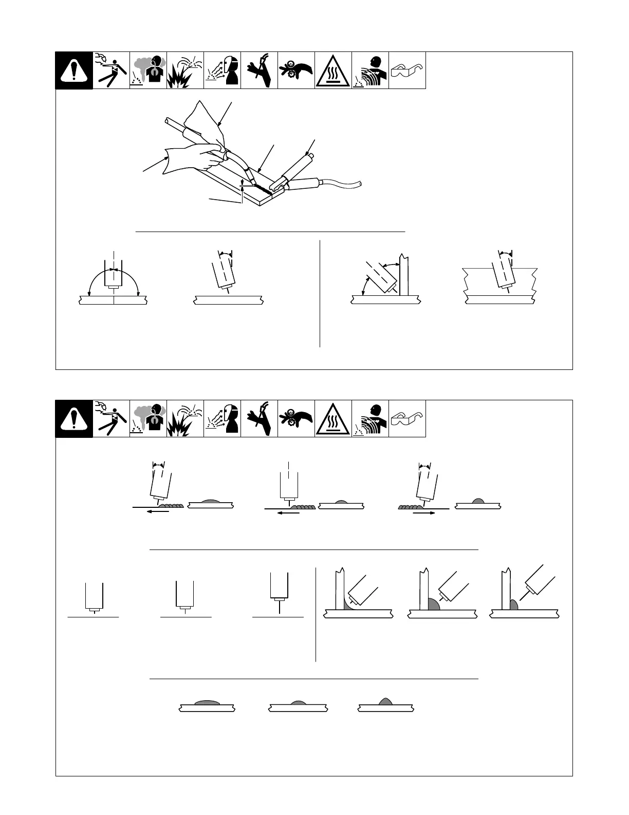
. Welding wire is energized when
gun trigger is pressed. Before
lowering helmet and pressing trig-
ger, be sure wire is no more than
1/2 in. (13 mm) past end of nozzle,
and tip of wire is positioned cor-
rectly on seam.
1 Hold Gun and Control Gun
Trigger
2 Workpiece
3 Work Clamp
4 Electrode Extension (Stickout)
Solid Wire − 3/8 to 1/2 in.
(9 to 13 mm)
5 Cradle Gun and Rest Hand on
Workpiece
2
3
5
4
90° 90°
0°-15°
45°
45°
1
0°-15°
S-0421-A
End View of Work Angle Side View of Gun Angle
Groove Welds
End View of Work Angle Side View of Gun Angle
Fillet Welds
10-3. Holding And Positioning Welding Gun
Slow
Fillet Weld Electode Extensions (Stickout)
Electrode Extensions (Stickout)
Gun Angles And Weld Bead Profiles
10°
10°
S-0634
Push
Perpendicular
Drag
Short Normal Long
Short Normal Long
Normal Fast
. Weld bead shape depends
on gun angle, direction of
travel, electrode extension
(stickout), travel speed,
thickness of base metal, wire
feed speed (weld current),
and voltage.
10-4. Conditions That Affect Weld Bead Shape
Gun Travel Speed