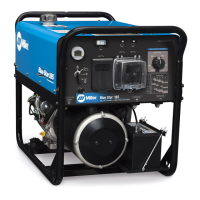
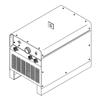
This document is an owner's manual for the Miller SRH-333, SRH-444, and SRH-500 arc welding power sources, published in July 2000. It provides comprehensive information on safety, installation, operation, maintenance, and parts for these industrial welding machines.
Function Description
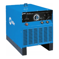
The Miller SRH-333, SRH-444, and SRH-500 are arc welding power sources designed for various welding and cutting processes. These units are capable of performing:
- Stick (SMAW) Welding: A common arc welding process that uses a consumable electrode covered with a flux to lay the weld.
- Air Plasma Cutting and Gouging: Processes that use a plasma torch to cut or gouge metal by melting it with a high-velocity jet of ionized gas.
- Air Carbon Arc (CAC-A) Cutting and Gouging: A cutting and gouging process that uses an arc between a carbon electrode and the workpiece, and compressed air to remove molten metal.
- Submerged (SAW) Welding: An arc welding process where the arc is submerged under a blanket of granular flux.
The units are described as "CC DC 3 Phase Arc Welding Power Source," indicating they provide Constant Current (CC) Direct Current (DC) output and operate on a three-phase input power supply.
Important Technical Specifications
The manual provides detailed specifications for the 300 Amp and 400 Amp models, including:
General:
- IP Rating: IP21M, indicating protection against solid objects larger than 12.5 mm and vertically falling water drops, with "M" signifying suitability for use while moving.
- No Load Voltage (Uo): Rated at 75V for both 300 Amp and 400 Amp models.
300 Amp Model (60 Hz):
- Rated Welding Output: 300 A at 32 Volts DC, 60% Duty Cycle.
- Amp Range DC: Low Range (A) 30-225 A, High Range (B) 40-375 A.
- Input Amperes at Rated Output (Three-Phase):
- 208V: 64A (4.8 kVA)
- 230V: 58A (4.3 kVA)
- 460V: 29A (2.2 kVA)
- Max Recommended Standard Fuse Rating (Time-Delay/Normal Operating):
- 208V: 80A/100A
- 230V: 70A/90A
- 460V: 35A/45A
- Min Input Conductor Size (AWG/Kcmil):
- 208V, 230V: 8 AWG/Kcmil
- 460V: 10 AWG/Kcmil
- Max Recommended Input Conductor Length (Feet/Meters):
- 208V: 101 ft (31 m)
- 230V: 124 ft (38 m)
- 460V: 332 ft (101 m)
- Min Grounding Conductor Size (AWG/Kcmil):
- 208V, 230V: 8 AWG/Kcmil
- 460V: 10 AWG/Kcmil
- Weight: 685 lb (311 Kg).
- Dimensions (Inches/Millimeters):
- A: 30-1/4 (768)
- B: 22-1/2 (571)
- C: 35-3/4 (908)
- D: 20 (508)
- E: 1-1/4 (32)
- F: 1-1/2 (38)
- G: 4-1/2 (114)
- H: 29-3/4 (755)
400 Amp Model (60 Hz):
- Rated Welding Output: 400 A at 36 Volts DC, 60% Duty Cycle.
- Amp Range DC: Low Range (A) 30-280 A, High Range (B) 50-500 A.
- Input Amperes at Rated Output (Three-Phase):
- 208V: 89A (5.8 kVA)
- 230V: 80A (5.3 kVA)
- 460V: 40A (2.6 kVA)
- 575V: 32A (2.1 kVA)
- Max Recommended Standard Fuse Rating (Time-Delay/Normal Operating):
- 208V: 110A/125A
- 230V: 100A/125A
- 460V: 50A/60A
- 575V: 40A/50A
- Min Input Conductor Size (AWG/Kcmil):
- 208V: 4 AWG/Kcmil
- 230V: 6 AWG/Kcmil
- 460V, 575V: 8 AWG/Kcmil
- Max Recommended Input Conductor Length (Feet/Meters):
- 208V: 171 ft (52 m)
- 230V: 142 ft (43 m)
- 460V: 375 ft (114 m)
- 575V: 395 ft (120 m)
- Min Grounding Conductor Size (AWG/Kcmil):
- 208V, 230V: 6 AWG/Kcmil
- 460V, 575V: 10 AWG/Kcmil
- Weight: 755 lb (342 Kg).
- Dimensions: Same as 300 Amp model.
400 Amp Model (50 Hz):
- Input Voltage: 220V, 380V, 440V.
- Input Amperes at Rated Output: 84A (220V), 48A (380V), 42A (440V).
- Max Recommended Standard Fuse Rating (Time-Delay/Normal Operating):
- 220V: 100A/125A
- 380V: 60A/70A
- 440V: 50A/60A
- Min Input Conductor Size (AWG/Kcmil):
- 220V: 4 AWG/Kcmil
- 380V, 440V: 8 AWG/Kcmil
- Max Recommended Input Conductor Length (Feet/Meters):
- 220V: 193 ft (59 m)
- 380V: 258 ft (79 m)
- 440V: 346 ft (105 m)
- Min Grounding Conductor Size (AWG/Kcmil):
- 220V: 6 AWG/Kcmil
- 380V, 440V: 8 AWG/Kcmil
Usage Features
- Amperage Adjustment Control: A central dial on the front panel allows users to adjust the welding amperage. It features an inner scale (A) for low amperage range and an outer scale (B) for high amperage range, corresponding to the Negative Weld Output Terminals.
- Remote Amperage Switch: A switch allows selection between front panel control ("Panel" position) and remote control ("Remote" position) for amperage adjustment. This enables flexibility in controlling the welding process from a distance.
- Remote Amperage Control Receptacle (RC1): For remote control, a plug is inserted and turned clockwise until tight.
- Power Switch: A simple ON/OFF switch for the unit.
- Optional Ammeter and Voltmeter: These gauges display the weld amperage output and voltage at the weld output terminals, respectively.
- Input Power Connection: The units are designed for three-phase input power. Jumper links inside the rear panel allow selection of different input voltages (e.g., 208V, 230V, 460V, 575V for 60Hz models; 220V, 380V, 440V for 50Hz models). The manual emphasizes checking available power and matching jumper link positions.
- Weld Output Terminals: The units feature a Positive (+) Weld Output Terminal and two Negative (-) Weld Output Terminals (Low Range A and High Range B). Users connect the work cable to the negative terminal that supplies the desired amperage range for DC Electrode Positive (DCEP) and the electrode holder cable to the positive terminal. For DC Electrode Negative (DCEN), cable connections are reversed. Only one negative weld output terminal should be used at a time.
- Duty Cycle: The duty cycle is the percentage of a 10-minute period that the unit can weld at its rated load without overheating. Exceeding the duty cycle can damage the unit and void the warranty. For example, a 60% duty cycle means 6 minutes of welding followed by 4 minutes of resting.
- Overload Protection: A Circuit Breaker (CB1) protects the welding power source control circuit from overload. If CB1 opens, the weld output drops to the minimum of the selected range, and the button needs to be pressed to reset it.
- Portability: The units are equipped with a lifting eye and can be moved using lifting forks. Caution is advised when moving over uneven surfaces.
Maintenance Features
- Routine Maintenance Schedule:
- Every 3 Months: Replace unreadable labels, repair or replace cracked weld cables, and clean and tighten weld terminals.
- Every 6 Months (or monthly during heavy service): Blow out or vacuum the inside of the unit. The bearings are sealed and do not require oil.
- Troubleshooting Table: A comprehensive table helps diagnose common issues such as no weld output, low or minimum weld output, low weld amperage not controlled by adjustment, maximum weld output, erratic or improper weld output, excessive line current/fuse opening, and fan not operating/overheating. It provides corresponding remedies, often directing users to specific sections of the manual for detailed instructions (e.g., checking input power connections, jumper link positions, weld connections, line voltage, circuit breakers, and remote amperage switch position).
- Electrical Diagrams: Detailed circuit diagrams (for 60 Hz and 50 Hz models) are provided, located inside the wrapper of the welding power source, to aid in servicing and repair by qualified personnel.
- Parts List: A comprehensive list of parts, including item numbers, diagram markings, part numbers, descriptions, and quantities for different models, is included. This facilitates ordering replacement parts.
- Factory/Authorized Service: The manual recommends replacing coils at a factory or authorized service station/service distributor and emphasizes using only manufacturer's suggested replacement parts to maintain original performance. Model and serial numbers are required when ordering parts.
- Safety Precautions: The manual extensively covers safety precautions, including warnings about electric shock, fumes and gases, arc rays, fire and explosion hazards, hot parts, magnetic fields (especially for pacemaker wearers), noise, falling units, overuse/overheating, static electricity (ESD) for PC boards, and moving parts. It also provides guidance on principal safety standards and EMF information.