EasyManua.ls Logo

Miller Syncrowave 210 User Manual

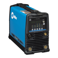
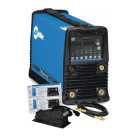
Miller Syncrowave 210
56 pages
To Next Page IconTo Next Page
Page #1 background imageLoading...
Page #1 background image
Processes
OM-261726G 2017-03
Processes
TIG (GTAW) Welding
Description
File: TIG (GTAW)
Syncrowave 210
)
Stick (SMAW) Welding
For product information,
Owner’s Manual translations,
and more, visit
www.MillerWelds.com

Table of Contents

Questions and Answers:

Miller Syncrowave 210 Specifications

General IconGeneral
BrandMiller
ModelSyncrowave 210
CategoryWelding System
LanguageEnglish

Summary

Section 1: Safety Precautions

Symbol Usage

Explains the meaning and usage of danger, warning, and notice symbols in the manual.

Arc Welding Hazards

Details hazards associated with arc welding, including electric shock, fumes, and fire.

Additional Symbols for Installation, Operation, and Maintenance

Covers symbols for fire, falling equipment, overheating, sparks, static discharge, moving parts, wire, and battery explosion.

California Proposition 65 Warnings

Warns about chemicals in fumes and gases known to cause birth defects or cancer.

Principal Safety Standards

Lists key safety standards and organizations relevant to welding equipment.

EMF Information

Explains electromagnetic fields (EMF) and precautions for users with medical implants.

Section 3: Definitions

Additional Safety Symbols and Definitions

Defines additional safety symbols used in the manual, like tip-over warnings.

Miscellaneous Symbols and Definitions

Provides definitions for various symbols related to electrical units, connections, and processes.

Section 4: Specifications

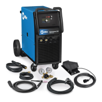
Included with Your Unit

Lists the components and accessories included with the welding unit.

Serial Number and Rating Label Location

Identifies the location of the serial number and rating label for the power source.

Specifications

Details electrical specifications like input power, output range, duty cycle, KVA, KW, and OCV.

Dimensions and Weights

Provides physical dimensions (A, B, C) and weight of the welding unit.

Duty Cycle Chart

Illustrates duty cycle percentages for different welding processes and input voltages.

Environmental Specifications

Outlines IP rating and temperature specifications for operating and storing the equipment.

Section 5: Installation

Selecting a Location

Guides on choosing a suitable location for the unit, considering airflow and movement safety.

Remote 14 Receptacle

Details the function and pin assignments of the 14-pin remote receptacle.

Shielding Gas Connections

Explains how to connect shielding gas, including cylinder valve, regulator, and flow adjustment.

Weld Output Connections

Describes how to connect the electrode holder, work clamp, and use the process selector.

Removing Power Pin Style Connector to Adapt Spoolmate 100/150 Models

Provides steps to remove the power pin connector from a spoolmate for compatibility.

Installing Dinse Style Connector to Adapt Spoolmate 100/150 Models

Details the procedure for installing a Dinse style connector for spoolmate compatibility.

Adapter Cord Connections to Adapt Spoolmate 100/150 Models

Explains how to connect adapter cords for spoolmate compatibility with the welding power source.

Electrical Service Guide

Provides recommendations for electrical service requirements, fuse ratings, and conductor sizes.

Selecting Extension Cord

Offers guidance on selecting extension cords based on input voltage and conductor size.

Connecting 115 Volts Input Power

Details the process for connecting the unit to a 115-volt AC input power supply.

Connecting 1-Phase Input Power

Provides instructions for connecting single-phase input power, including safety precautions.

Multi-Voltage Plug (MVP) Connection

Explains how to connect multi-voltage plugs for different power supply receptacles.

Section 6: Operation

Syncrowave 210 Controls Overview

Identifies and describes the main controls and indicators on the Syncrowave 210 front panel.

Accessing Control Panel Menu: AC TIG

Guides on navigating the AC TIG control panel menu and adjusting parameters.

Accessing DC TIG Control Panel Menu

Details how to access and use the DC TIG control panel menu and its settings.

Accessing DC Stick Control Panel Menu

Explains how to navigate the DC Stick control panel menu and adjust settings.

Accessing Spool Gun Control Panel Menu

Describes how to access and configure settings for the spool gun control panel.

Accessing User Setup Menu: AC and DC TIG

Guides on using the user setup menu for AC and DC TIG welding parameters.

Accessing User DC Stick Setup Menu

Details how to access and configure settings within the user DC Stick setup menu.

Accessing User Spool Gun Setup Menu

Explains how to access and set parameters for the spool gun user setup menu.

Section 7: Advanced Menu Functions

Accessing Tech Menu

Describes how to access and utilize the advanced Tech Menu for machine configuration.

Section 9: Electrical Diagrams

Section 10: High Frequency

Welding Processes Requiring High Frequency

Identifies welding processes that typically require high-frequency (HF) starting.

Installation Showing Possible Sources of HF Interference

Illustrates common sources of High Frequency (HF) interference in a welding setup.

Recommended Installation to Reduce HF Interference

Provides guidelines for installing the equipment to minimize High Frequency (HF) interference.

Section 11: Selecting and Preparing Tungsten

Selecting Tungsten Electrode

Guides on selecting tungsten electrodes based on diameter, amperage, and polarity.

Preparing Tungsten Electrode for DCEN or AC Welding

Explains the proper method for grinding tungsten electrodes to ensure stable arc performance.

Section 12: Guidelines for TIG Welding (GTAW)

Positioning the Torch

Details the correct torch positioning and angle for optimal TIG welding.

Torch Movement During Welding

Illustrates proper torch movement techniques with and without filler rod.

Positioning Torch Tungsten for Various Weld Joints

Shows correct tungsten positioning for different weld joint types like butt, lap, and corner.

Section 13: Stick Welding (SMAW) Guidelines

Stick Welding Procedure

Outlines the basic procedure for stick welding, including safety and equipment.

Electrode and Amperage Selection Chart

Provides a chart for selecting electrodes and corresponding amperage ranges.

Striking an Arc

Explains two methods for striking an arc: scratch and tapping techniques.

Positioning Electrode Holder

Guides on the correct positioning of the electrode holder for groove and fillet welds.

Poor Weld Bead Characteristics

Illustrates common defects in weld beads such as spatter, overlap, and poor penetration.

Good Weld Bead Characteristics

Shows examples of good weld bead characteristics like uniformity and proper penetration.

Conditions That Affect Weld Bead Shape

Explains how electrode angle, arc length, and travel speed influence weld bead shape.

Electrode Movement During Welding

Describes electrode movement patterns for stringer and weave beads.

Welding Lap Joints

Details procedures for welding lap joints, including single and multi-layer deposits.

Welding Groove (Butt) Joints

Covers techniques for welding butt joints, including tack welds and groove preparation.

Welding Tee Joints

Provides guidance on welding tee joints, including fillet welds and multi-layer deposits.

Weld Test

Describes how to perform a weld test to evaluate weld quality and identify causes of failure.

Troubleshooting Stick Welding

Lists common weld defects like porosity and spatter with their possible causes and corrective actions.

Warranty Information

Limited Warranty Details

Outlines the limited warranty terms, coverage periods, and exclusions for Miller equipment.

Owner's Record and Service Information

For Service and Parts

Provides contact information for service, distributors, and ordering parts.

Related product manuals