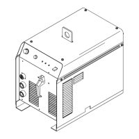
. A complete Parts List is available at www.MillerWelds.com
OM-261726 Page 32
8-3. Meter Troubleshooting Displays
. All directions are in reference to the
front of the unit. All circuitry referred to
is located inside the unit.
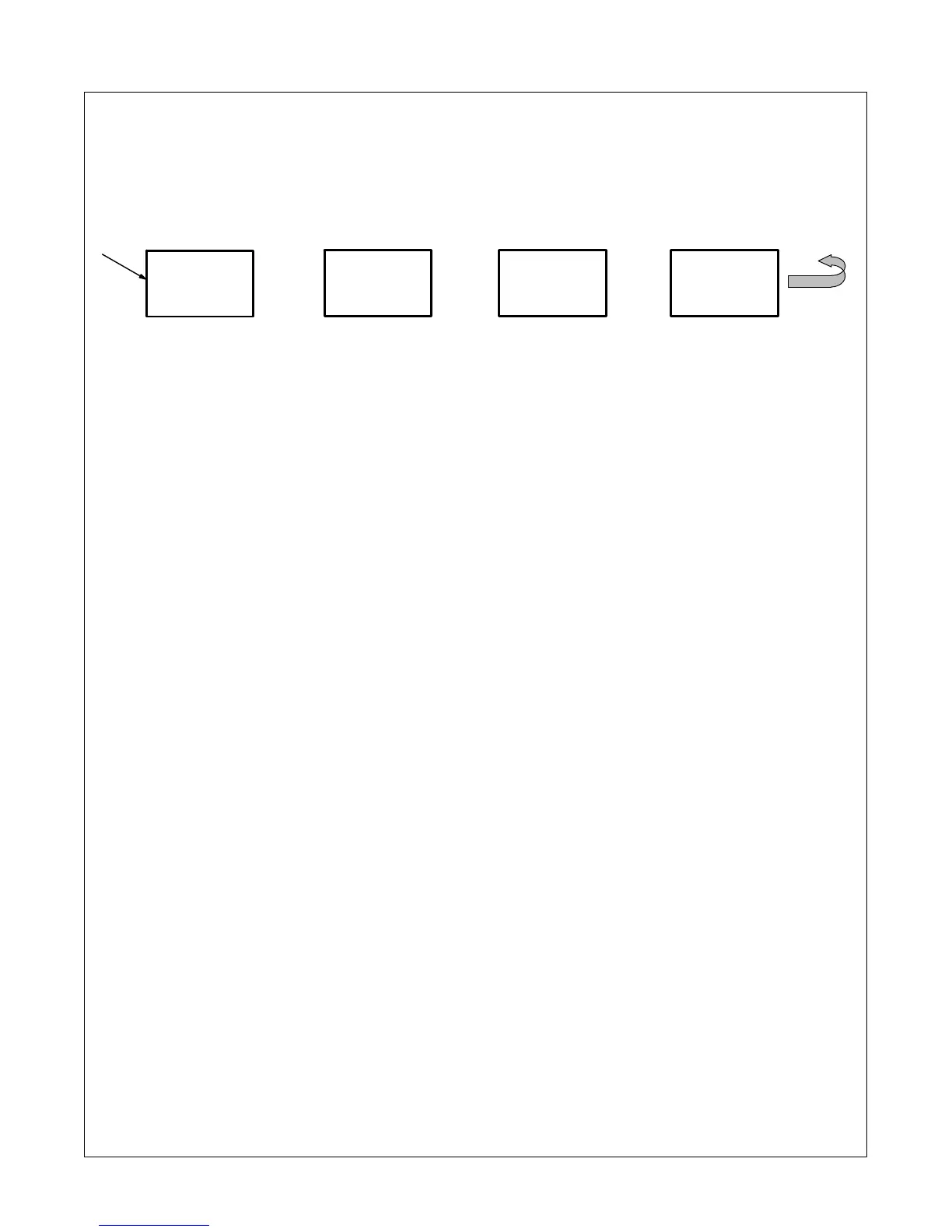
1 Typical meter display may be in
several segments. Each segment is
shown for two seconds, and then
scrolls to the remaining segments
of the display. The message then
repeats itself.
Release Trigger Error:
w [RELE] [ASE]/[TRIG] [GER]
Remote 14 receptacle contactor control
(Pins A−B) must be opened before pro-
ceeding.
Communication Errors:
w [SCOM] [SD]
Serial Communication to the memory card
board has been lost. To clear error, turn off
power. If error does not clear or happens
frequently, contact a Factory Authorized
Service Agent.
w [SCOM] [UI]
Serial Communication to the user interface
card board has been lost. To clear error, turn
off power. If error does not clear or happens
frequently, contact a Factory Authorized
Service Agent.
Over Temperature Errors:
w [INV] [OT]
Over temperature condition in the primary
inverter circuitry has occurred. Error will
clear after the temperature has reached ac-
ceptable levels.
w [PFC] [OT]
Over temperature condition in the primary
power factor correction circuitry has oc-
curred. Error will clear after the temperature
has reached acceptable levels.
w [SEC] [OT]
Over temperature of the weld output circuit-
ry has occurred. Error will clear after the
temperature has reached acceptable
levels.
Temperature Sensor Failure:
w [INV] [ERRT]
Indicates a short or open in the thermal pro-
tection circuitry located in the primary in-
verter circuitry of the unit. Contact a Factory
Authorized Service Agent if this display is
shown.
w [PFC] [ERRT]
Indicates a short or open in the thermal pro-
tection circuitry located in the primary pow-
er factor correction circuitry of the unit. Con-
tact a Factory Authorized Service Agent if
this display is shown.
w [SEC] [ERRT]
Indicates a short or open in the thermal pro-
tection circuitry located in the weld output
circuitry of the unit. Contact a Factory Au-
thorized Service Agent if this display is
shown.
Latching Errors:
w [CLMP] [ERR]/[OVER] [VOLT]
Secondary clamp voltage too high.
Straighten out or shorten weld cables. If this
does not correct the problem, contact a
Factory Authorized Service Agent.
w [CLMP] [ERR]/[OVER] [AMPS]
Secondary clamp amperage too high.
Straighten out or shorten weld cables. If this
does not correct the problem, contact a
Factory Authorized Service Agent.
Not Valid Error:
w [Not] [Valid]
Indicates a non-allowable set-up on the
front panel.
1
RELE
ASE
....
2 Sec
TRIG
Repeat
GER