. A complete Parts List is available at www.MillerWelds.com
OM-261726 Page 23
SECTION 6 − OPERATION
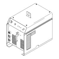
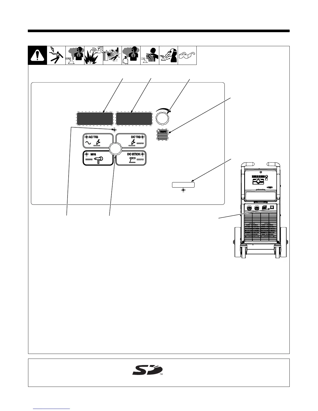
6-1. Syncrowave 210 Controls
268890-B/ 805521-A
1 Amperage Adjustment Control
Use control to change preset amperage
value. If a remote control is used, preset
amperage value is the maximum amperage
output available. This control also functions
as a parameter change control while in the
menu mode (see Sections 6-2 thru 6-7).
2 Memory Card Port And Indicator
This port is used to add features to the ma-
chine and update software to the boards
within the machine. Indicator is lit while card
is being accessed.
3 Volt Meter
Displays actual voltage when voltage is
present at the weld output terminals. It is
also used to display parameter descrip-
tions while in the menu.
4 Ammeter
Displays actual amperage while welding
and preset amperage while idle. It is also
used to display parameter selection op-
tions while in the menu.
5 Menu Button
Press button to scroll through available
parameters for the selected process. Hold
button to enter set-up mode (see Sections
6-2 thru 6-7).
6 Output ON Indicator
Blue indicator illuminates when output is
on.
7 Process Selector
Use to select one of the following pro-
cesses:
• AC TIG - Used for welding aluminum.
• DC TIG - (DCEN) Used for welding mild
and stainless steel.
• DC Stick - (DCEP) Used for welding
steels.
• MIG - (Optional Expansion)
8 Power Switch
5
4
3
7
1
2
6
8
The memory card port uses an SD
memory card.
SD Logo is a trademark of the 3C.